
Method of determining impact-load equivalent static load

An impact load and static load technology, applied in the direction of elasticity test, machine/structural component test, force/torque/work measuring instrument, etc., can solve the problems of excessive safety factor, conservative design, lack of theoretical basis, etc. The theoretical basis is sufficient, the authenticity is improved, and the application range is wide.

Active Publication Date: 2017-05-24
XIAN AIRCRAFT DESIGN INST OF AVIATION IND OF CHINA
View PDF4 Cites 3 Cited by
  • Summary
  • Abstract
  • Description
  • Claims
  • Application Information

AI Technical Summary

Problems solved by technology

The disadvantage is that this method lacks a rigorous theoretical basis, and the solution formula of the dynamic scaling coefficient adopts approximate values, and all of them are greater than 1
Therefore, the equivalent static load obtained by using this method is always greater than the peak value of the impact load, which makes the safety factor too large, resulting in a conservative design

Method used


Image

  • Method of determining impact-load equivalent static load
  • Method of determining impact-load equivalent static load
  • Method of determining impact-load equivalent static load

Examples


Embodiment 1

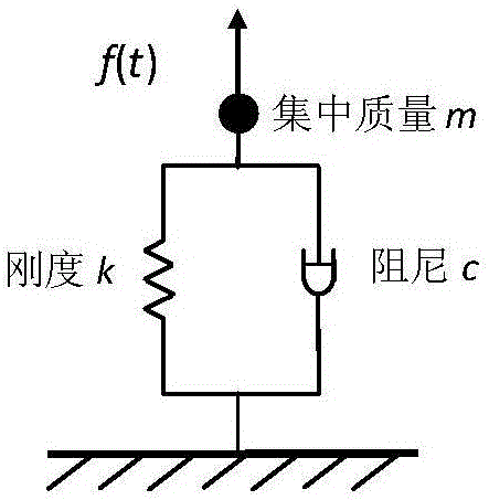
[0094] Take a beam structure as an example to illustrate the implementation process of determining the equivalent static load of impact load based on this method.

[0095] 1. Establish a finite element model of the beam structure

[0096] Image 6 Shows a schematic diagram of a beam structure. The beam is 2m long and has an included angle of 45o with the negative direction of the OY axis. The cross section is an equal straight circular ring with an outer diameter of 0.05m and an inner diameter of 0.04m. The material is alloy steel, the elastic modulus of the material is 200GPa, the Poisson's ratio is 0.3, and the density is 7800kg / m 3 . A linear spring is arranged at 1 / 10 of one end of the beam close to the origin O, which only provides Y-direction stiffness for adjusting the bending frequency of the beam around the OZ axis. MSC.PATRAN is used to establish the finite element model of the structure.

[0097] 2. Calculate the natural frequency of the finite element model

[0098] Set...

Embodiment 2

[0115] Taking the water forced precipitation load measurement test of a certain aircraft scale model as an example, the process of determining the equivalent static pressure of the water forced landing based on this method is explained.

[0116] 1. Determine P and T D

[0117] Figure 8 Shows the time history of pressure somewhere on the fuselage on the test side. It can be seen that the first peak impact pressure P=900kPa. according to Figure 5 The method shown determines T E =0.006s, therefore, the duration T D =2.5T E = 0.015s.

[0118] 2. Determine f n

[0119] According to the aircraft ground resonance test, the first-order natural frequency of the fuselage is 9 Hz, so f n = 9 Hz.

[0120] 3. Calculate the dynamic scaling factor λ

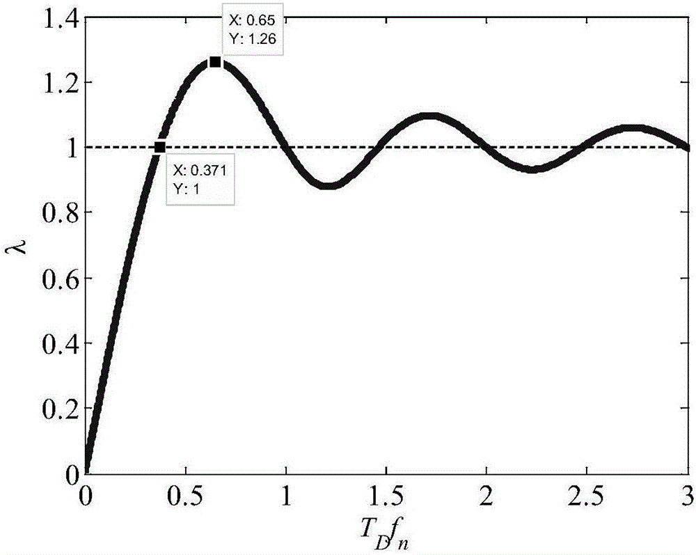
[0121] Dimensionless parameter f n T D =0.848, the dynamic scaling factor λ=0.415 obtained according to formula (20).

[0122] 4. Calculate the equivalent static pressure

[0123] Equivalent static pressure is P s =λP=0.415×900=374kPa.


PUM

PropertyMeasurementUnit
Elastic modulusaaaaaaaaaa
Densityaaaaaaaaaa

Abstract

The invention belongs to the structure and equipment impact resistance design technology field and relates to a method of determining an impact-load equivalent static load. The method comprises the following steps of step1, according to the following formula which is defined in the description, calculating a dynamic scaling coefficient lambda, wherein TD is duration of an impact load, and fn is a fundamental frequency of a structure to be impacted; and step2, according to the following formula, calculating an equivalent static load Ps of the impact load, wherein the formula is Ps=lambda P, and the P is a peak value of the impact load. A lambda value acquired through calculation in the scheme can be greater than and less than 1 according to a change of TDfn, which is really equivalent to the impact load, and a truth degree of the equivalent static load is increased.

Description

Technical field [0001] The invention belongs to the technical field of structure and equipment impact resistance design, and relates to a method for determining the equivalent static load of the impact load. Background technique [0002] The said equivalent static load refers to equipment and structures that are inconvenient or even impossible to directly perform impact simulation or test, and the impact load is equivalent to static load, so as to provide input for equivalent static simulation or test of impact. [0003] The document "Structural Design Method under Impact Load" (Missile and Space Carrier Technology, 2007 Issue 3: 33~37) gives a formula to determine the equivalent static load of impact load: [0004] [0005] Where: T D Is the duration of impact load; ω n Is the natural circular frequency of the system; λ is the dynamic scaling factor, which is defined as the equivalent static load P s Ratio to peak impact load P: [0006] [0007] When the natural circular frequency ω...

Claims


Application Information

Patent Timeline
IPC IPC(8): G01L5/00G01M5/00
CPCG01L5/0052G01M5/0075
Inventor 张玉杰冯震宙黄超广
Owner XIAN AIRCRAFT DESIGN INST OF AVIATION IND OF CHINA
Learn More