Pressure sensor cooling device applicable to high-temperature environment test

A pressure sensor and cooling device technology, applied in the direction of measuring devices, measuring fluid pressure, instruments, etc., can solve problems such as large measurement errors, achieve the effects of strengthening heat loss, improving thermal adaptability, and improving thermal adaptability

Active Publication Date: 2017-05-24
HUANENG POWER INTERNATIONAL +1
View PDF17 Cites 9 Cited by
  • Summary
  • Abstract
  • Description
  • Claims
  • Application Information

AI Technical Summary

Problems solved by technology

This test method is more suitable for dynamic pressure measurement of low-frequency pulsating fluid working medium, but for high-frequency unsteady-state pulsating working medium, after using a long pressure induction tube, the pressure signal measured by the sensor is consistent with the real pressure of the fluid working medium. The amplitude-frequency and phase-frequency characteristics between the signals will be quite different, and the measurement error is proportional to the length of the pressure induction tube. The longer the pressure induction tube, the greater the measurement error

Method used


Image

  • Pressure sensor cooling device applicable to high-temperature environment test
  • Pressure sensor cooling device applicable to high-temperature environment test
  • Pressure sensor cooling device applicable to high-temperature environment test

Examples


Embodiment

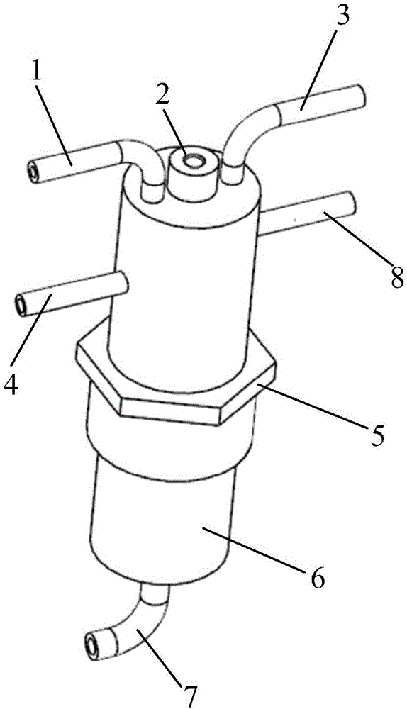
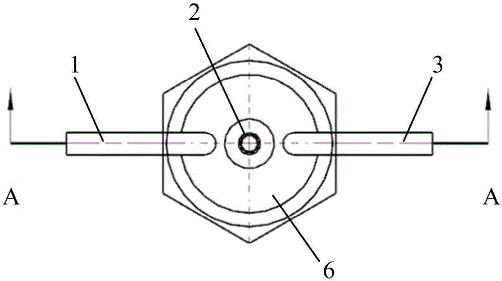
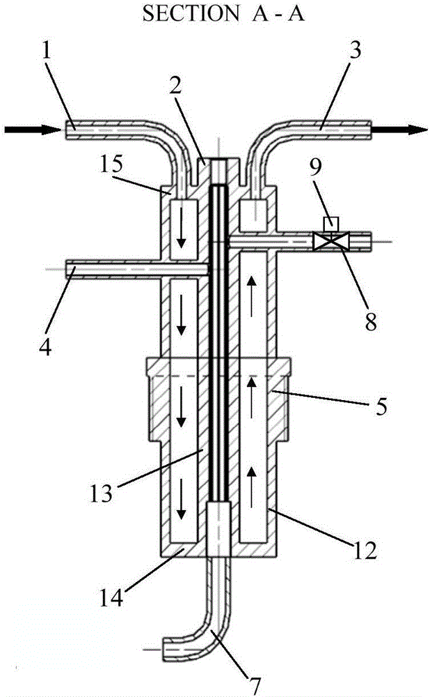
[0039] In this embodiment, the cooling heat exchange structure 6 is 80mm long, and the outer wall 12 of the cooling chamber is coaxially arranged with the inner wall 13 of the cooling chamber. The outer diameter of the outer wall 12 of the cooling chamber is 25 mm, the inner diameter is 21 mm, and the wall thickness is 2 mm. The inner diameter is 5mm and the wall thickness is 2mm. On the inner surface of the cooling cavity inner wall 13 and the cooling cavity bottom plate 14, there is a 15mm long M6×0.5 standard internal thread, and the cooling cavity bottom plate 14 and the cooling cavity cover plate 15 have a wall thickness of 2mm; The plate 10 is 70 mm long and 2 mm thick, and is connected with the outer wall 12 of the cooling chamber and the inner wall 13 of the cooling chamber, and divides the annular space formed between the outer wall 12 of the cooling chamber and the inner wall 13 of the cooling chamber into a left semicircle cooling flow path 16 and a right semicircle ...


PUM


Abstract

The invention discloses a pressure sensor cooling device applicable to a high-temperature environment test. The pressure sensor cooling device comprises a cooling heat exchange structure with a hollow cavity, wherein the hollow cavity of the cooling heat exchange structure is divided into an inner cavity and an outer cavity; the outer cavity is separated into two parts of which bottoms are communicated with each other; a cooling water inlet pipe communicated with one part of the outer cavity and a cooling water outlet pipe communicated with the other part of the outer cavity are arranged on the top of the cooling heat exchange structure; a sensor mounting seat is arranged on the top of the inner cavity, a pressure drawing pipe is arranged at the bottom of the inner cavity; and a temperature sensor mounting seat which penetrates through one part of the outer cavity and is communicated with the inner cavity, and a nitrogen supply pipe which penetrates through the other part of the outer cavity and is communicated with the inner cavity are arranged in the peripheral direction of the cooling heat exchange structure. According to the pressure sensor cooling device disclosed by the invention, dynamic pressure measurement errors of unsteady fluid media in the existing high-temperature environment can be reduced.

Description

[0001] Technical field: [0002] The invention relates to a pressure sensor cooling structure, in particular to a pressure sensor cooling device suitable for high-temperature environment testing. [0003] Background technique: [0004] Pressure is an important state parameter that characterizes the hydrodynamic properties of the object under study. For an unsteady flow process, the state parameters such as the pressure and temperature of the working fluid will change with time and have dynamic characteristics. At present, dynamic pressure is widely used in the fields of industrial production and scientific research. For example, the pressure in internal combustion engines, gas turbines, steam turbines, and rocket engines is basically dynamic. The chamber pressure of guns and explosion shock waves are dynamic pressure. Various industrial control equipment And the pulse pressure of hydraulic and pneumatic devices in power machinery is also dynamic pressure. Therefore, it is nece...

Claims


Application Information

Patent Timeline
IPC IPC(8): G01L19/06
CPCG01L19/0681
Inventor 肖俊峰李晓丰王峰王玮
Owner HUANENG POWER INTERNATIONAL
Why Eureka
Try Eureka