Polluted soil detection method based on three-dimensional high-density electrical resistivity method

A high-density resistivity and detection method technology, which is applied in the field of contaminated soil detection based on the three-dimensional high-density resistivity method, can solve problems such as inconsistent measurement conditions, and achieve reliable detection results, low input costs, and short acquisition cycles.

Inactive Publication Date: 2017-05-24
SHANGHAI GEOTECHN INVESTIGATIONS & DESIGN INST
View PDF5 Cites 13 Cited by
  • Summary
  • Abstract
  • Description
  • Claims
  • Application Information

AI Technical Summary

Problems solved by technology

[0004] The purpose of the present invention is to provide a method for detecting contaminated soil based on the three-dimensional high-density resistivity method according to the shortcomings of the above-mentioned prior art. The problem of inconsistent measurement conditions due to multiple detections

Method used


Image

  • Polluted soil detection method based on three-dimensional high-density electrical resistivity method
  • Polluted soil detection method based on three-dimensional high-density electrical resistivity method
  • Polluted soil detection method based on three-dimensional high-density electrical resistivity method

Examples


Embodiment 1

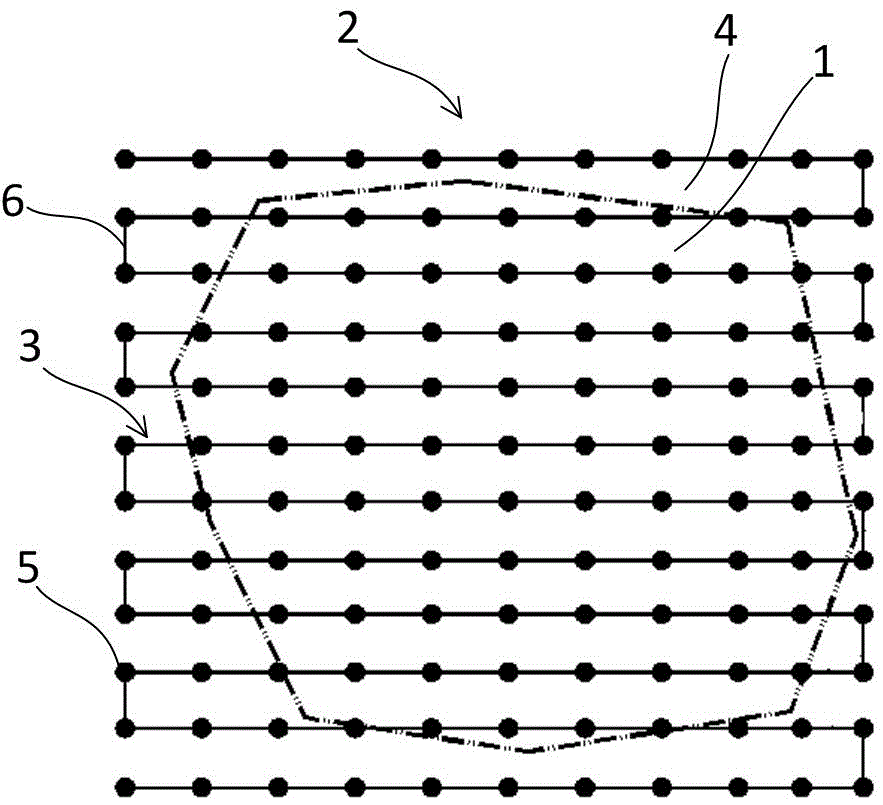
[0019] Embodiment 1: as figure 1 As shown, this embodiment specifically relates to a method for detecting contaminated soil based on a three-dimensional high-density resistivity method, the method comprising the following steps:

[0020] Such as figure 1 As shown, the planar detection unit area 2 is arranged in the pollution area 1, and the measuring line 3 is arranged in the planar detection unit area 2; in this embodiment, the pollution area 1 ( figure 1 The number of planar detection unit areas 2 within the middle dotted circle) is one, and the coverage of planar detection unit area 2 includes the polluted area 1 and the uncontaminated area 4 outside the polluted area 1 ( figure 1 outside the dotted circle).

[0021] In this embodiment, the measuring line 3 includes detection electrodes 5 distributed in the area 2 of the planar detection unit in an equidistant lattice form and a single detection cable 6 sequentially connected to each detection electrode; the detection cab...

Embodiment 2

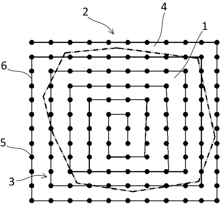
[0026] Embodiment 2: as figure 2 As shown, the main difference between this embodiment and embodiment 1 lies in the arrangement of the detection cable 6 in the measuring line 3; in this embodiment, the detection cable 6 is arranged inside the area 2 of the planar detection unit in a zigzag manner; The detection cables 6 are distributed in a rectangular spiral form gradually from the edge of the planar detection unit area 2 to the center.

Embodiment 3

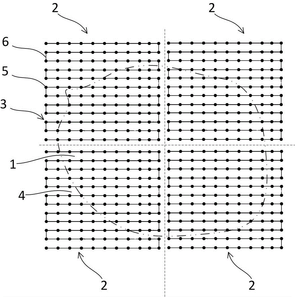
[0027] Embodiment 3: as image 3 As shown, the main difference between this embodiment and Embodiment 1 and Embodiment 2 lies in the number of planar detection unit regions 2 . From the above content, it can be known that the longer the length of the measuring line 3 in one direction of the high-density resistivity method, the greater the detection depth, but the lower the accuracy; therefore, for the polluted area 1 with a huge area, it is impossible to use a single planar detection unit area 2 to cover.

[0028] In this embodiment, the contaminated area 1 is covered by four planar detection unit areas 2; in order to obtain the comparison value, the coverage of the planar detection unit area 2 in this embodiment includes the contaminated area 1 and the area outside the contaminated area 1. Uncontaminated area 4. A measuring line 3 of a high-density resistivity method is arranged inside each planar detection unit area 2; the measuring line 3 can adopt the bow-shaped wiring i...


PUM


Abstract

The invention discloses a polluted soil detection method based on a three-dimensional high-density electrical resistivity method. The polluted soil detection method comprises the following steps that a facet-shaped detection unit zone is arranged in a polluted region, measuring lines are arranged in the facet-shaped detection unit zone and include a plurality of detection electrodes distributed in the facet-shaped detection unit zone in a uniformly-spaced dot matrix mode and single or multiple serially connected detection cables sequentially connected with the detection electrodes; electrical resistivity data of the detection electrodes of the measuring lines are acquired; three-dimensional inversion processing is conducted on the electrical resistivity data to obtain corresponding electrical resistivity profile data; the polluted region resistivity data measured by the measuring lines and electrical resistivity data of a non-polluted region are compared, and meanwhile the pollutant distribution in the polluted region is judged by combining with the electrical resistivity profile data. The polluted soil detection method has the advantages the time condition, power supply condition, electrode grounding condition and the like for data acquisition have consistency, and accordingly obtained electrical resistivity values have comparability and contrast.

Description

technical field [0001] The invention relates to the field of geotechnical engineering detection and testing, in particular to a contaminated soil detection method based on a three-dimensional high-density resistivity method. Background technique [0002] Nowadays, the scale of manufacturing industry is constantly expanding, the level of urbanization is constantly improving, and the social economy is developing vigorously. However, with the development of science and technology and the improvement of people's living standards, environmental pollution has become increasingly serious, causing serious damage to the ecosystem, affecting the quality of life, health and living activities of human beings, and causing a series of social problems. restricted economic development. Among the major pollution problems, land pollution has also become a more serious problem. The most harmful types include heavy metals, petroleum hydrocarbons, persistent organic pollutants, other industrial...

Claims


Application Information

Patent Timeline
Patent Type & Authority Applications(China)
IPC IPC(8): G01N27/04G01V3/00
CPCG01N27/041G01V3/00
Inventor 黄永进胡绕朱黎明马文亮王水强
Owner SHANGHAI GEOTECHN INVESTIGATIONS & DESIGN INST
Why Eureka
Try Eureka