
Photovoltaic power generation system control method for tracking through maximum power point spinning reserve capacity

A technology of spinning reserve capacity and photovoltaic power generation system, which is applied in photovoltaic power generation, control/regulation system, and regulation of electrical variables, etc., and can solve the problem of affecting the stability and dynamic response of the power system, not participating in power grid frequency regulation and voltage regulation, and transient response Fast speed and other issues, to achieve the effect of good grid-connected characteristics, economicalization, and high efficiency

Active Publication Date: 2017-05-24
NORTH CHINA ELECTRIC POWER UNIV (BAODING)
View PDF7 Cites 15 Cited by
  • Summary
  • Abstract
  • Description
  • Claims
  • Application Information

AI Technical Summary

Problems solved by technology

[0004] At the same time, most of the power electronic equipment that participates in the grid connection of distributed power sources is controlled by digital circuits, with fast transient response and almost no inertia, and does not participate in frequency regulation and voltage regulation of the power grid.
It is difficult for them to operate independently and autonomously like synchronous generators, and a large number of connections will seriously affect the stability and dynamic response of the power system

Method used


Image

  • Photovoltaic power generation system control method for tracking through maximum power point spinning reserve capacity
  • Photovoltaic power generation system control method for tracking through maximum power point spinning reserve capacity
  • Photovoltaic power generation system control method for tracking through maximum power point spinning reserve capacity

Examples


Embodiment Construction

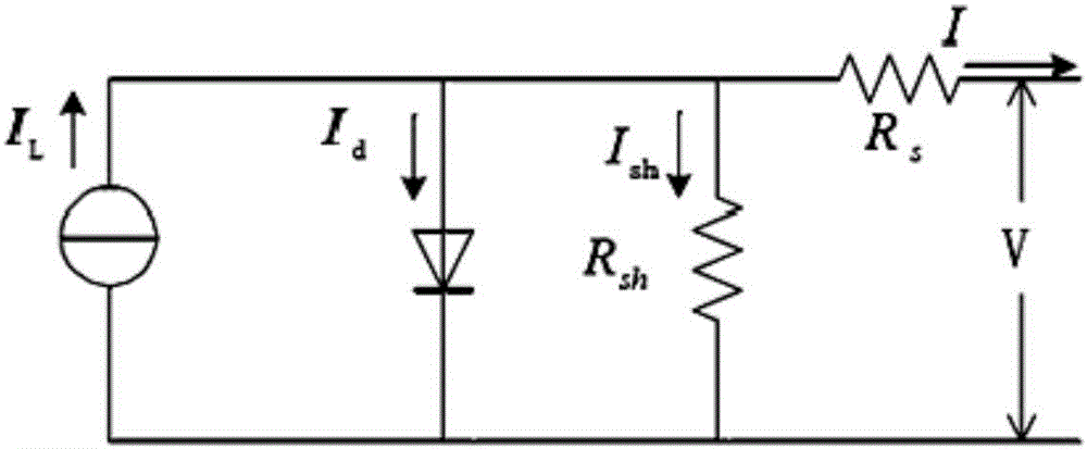
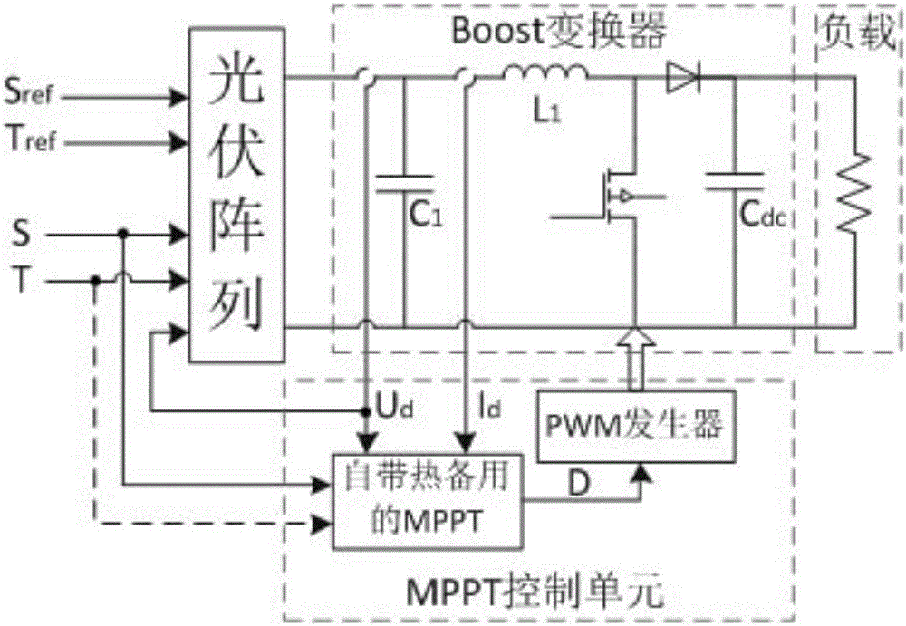
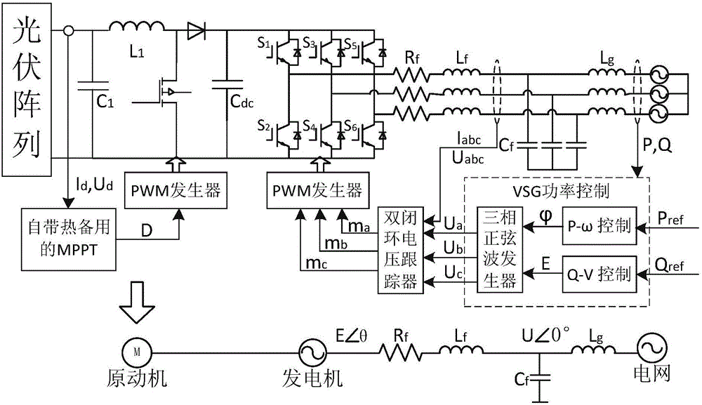
[0029] The present invention proposes a photovoltaic power generation system control method based on maximum power point rotating reserve capacity tracking. The present invention will be described in detail below in conjunction with the accompanying drawings.

[0030] In order to introduce the technical solution of the present invention, the principle of the present invention is firstly described.

[0031] The parameter meaning used in the present invention is:

[0032] I out is the photovoltaic cell output current,

[0033] I L is the photogenerated current inside the photovoltaic cell,

[0034] I d is the diode forward current,

[0035] R sh is the shunt resistor,

[0036] R S is the series resistance,

[0037] I SC is the short circuit current,

[0038] V OC is the open circuit voltage,

[0039] I m is the maximum output current,

[0040] u m is the maximum output voltage,

[0041] α is the short-circuit current temperature coefficient,

[0042] β is the o...


PUM


Abstract

The invention discloses a photovoltaic power generation system control method for tracking through maximum power point spinning reserve capacity in the technical field of power electronic control. The method comprises the following steps: acquiring photovoltaic cell performance parameters, and converting a photovoltaic cell circuit into an equivalent circuit; determining an initial discriminant relation between output power and output voltage under the condition of tracking the maximum power point of the photovoltaic cell according to the condition that a photovoltaic array output characteristic curve is a single peak curve; changing the power tracking point according to the selection standard of the spinning reserve capacity of the system; simulating mechanical inertia of a synchronous generator, frequency modulator and excitation controller characteristics and a double closed loop control by taking inductive current as inner loop feedback by adopting a VSG power controller according to the relation between the external environment and the photovoltaic array output characteristic curve, and determining the PV-VSG inertia and damping parameters. The maximum power point of the power generation load of a real-time synchronous tracking system at the spinning reserve capacity and the real-time tracking function in a transient stable state can be realized.

Description

technical field [0001] The invention belongs to the technical field of electric power electronic control, and in particular relates to a photovoltaic power generation system control method based on maximum power point rotating reserve capacity tracking. Background technique [0002] In recent years, with the rapid increase in the penetration rate of distributed power sources based on power electronic devices in power systems, some countries and regions such as China, the European Union, and the United States have formulated their own distributed energy development plans. [0003] As an important part of distributed power generation, photovoltaic power generation effectively solves the current social problem of energy shortage. However, due to the nonlinear characteristics of the output voltage and output current of the photovoltaic array affected by the external environment, its output power also changes continuously. Therefore, how to adjust the load characteristics to achi...

Claims


Application Information

Patent Timeline
Patent Type & Authority Applications(China)
IPC IPC(8): G05F1/67
CPCG05F1/67Y02E10/56
Inventor 颜湘武华天琪
Owner NORTH CHINA ELECTRIC POWER UNIV (BAODING)
Learn More