Coil rack assembly of electromagnetic relay

A technology of electromagnetic relays and coil formers, applied in electromagnetic relays, detailed information of electromagnetic relays, relays, etc., can solve the problems of pulling out the lead pins, affecting the high power of the relay, and difficult to meet the strength of the coil lead pins. , to achieve the effect of increasing the contact load capacity

Inactive Publication Date: 2017-05-24
宁波华仑电子有限公司
View PDF6 Cites 4 Cited by
  • Summary
  • Abstract
  • Description
  • Claims
  • Application Information

AI Technical Summary

Problems solved by technology

The disadvantage of this structural form of the relay coil frame assembly is that the winding end of the lead pin occupies the winding space of the enameled wire, which affects the high power of the relay under a certain volume limit.
The current electromagnetic relay also adopts an installation method in which the lead pin does not extend out o

Method used


Image

  • Coil rack assembly of electromagnetic relay
  • Coil rack assembly of electromagnetic relay
  • Coil rack assembly of electromagnetic relay

Examples


Embodiment 1

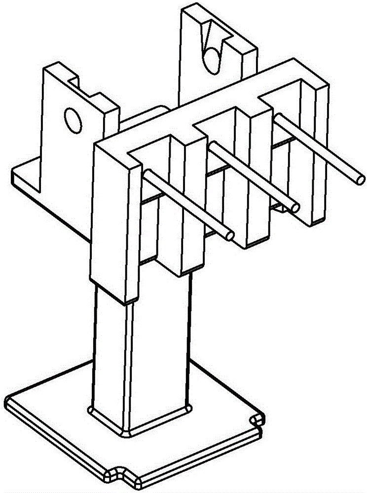
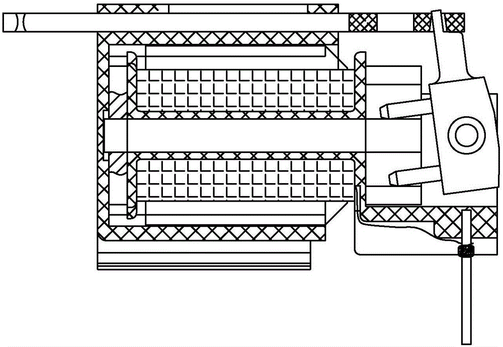
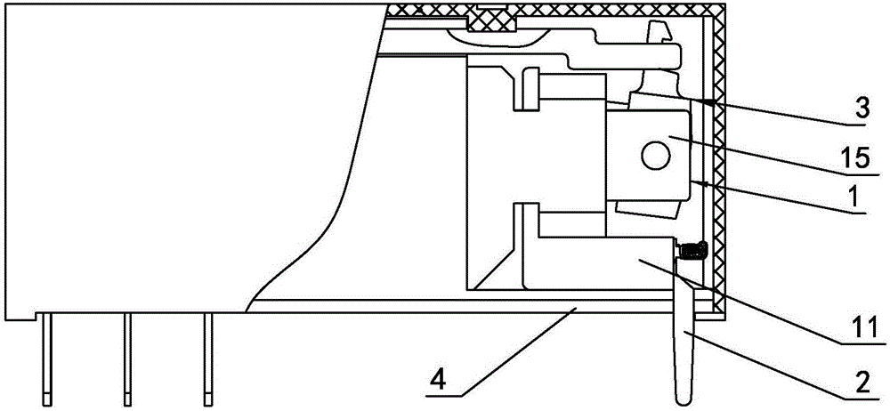
[0024] Embodiment one, such as Figure 3 to Figure 6 As shown, a coil frame assembly of an electromagnetic relay includes a coil frame 1 and a lead pin 2, and the coil frame 1 includes a lead pin mounting seat 11, a bobbin 12, and first flanges 13 and 12 arranged at both ends of the bobbin 12 The second flange 14, the lead foot mounting seat 11 is integrally connected to the lower end of the first flange 13, and the left and right sides of the first flange 13 are integrally provided with a left mounting plate 15 and a right mounting plate for installing the magnetic package 3 respectively. Plate 16, the length a of the lead pin mounting seat 11 is less than the length b of the left mounting plate 15 and the right mounting plate 16, and two first lead wire slots 17 with one end connected to the bobbin 12 are provided on the inner side of the first flange 13 , the other end of each first lead groove 17 is connected with one end of the corresponding second lead groove 18 arranged...

Embodiment 2

[0025] Embodiment two, such as Figures 7 to 10 As shown, its technical features are the same as those in Embodiment 1, the difference is that the number of second lead slots 18 is three, the clamping part 21 is not T-shaped as a whole, and the vertical section of the lead-out pin 1 is the same as the vertical section of the clamping part 21. Or the vertical section of the end wire part 22 is perpendicular to each other. In this way, after the clamping part 21 of the lead pin 2 is clamped with the slot 111, the contact area perpendicular to the clamping part 21 and the lead pin 2 reaches the maximum, so that the lead pin 2 and the lead pin 2 are perpendicular to each other. The installation and connection of the coil frame 1 is stable, and the insertion and extraction force that the lead pin 2 can withstand is also maximized.


PUM


Abstract

The invention discloses a coil rack assembly of an electromagnetic relay. The coil rack assembly comprises a coil rack and a terminal pin, wherein a terminal pin installation base is arranged on the coil rack; a clamping slot is arranged on the terminal pin installation base. The coil rack assembly is characterized in that the terminal pin comprises a clamping part, a terminal winding part and a leading foot perpendicular to the clamping part and the terminal winding part, wherein the clamping part and the terminal wire winding part are arranged back to back; the notch of the clamping slot is arranged on the side face of the terminal pin installation base; the clamping part of the terminal pin is connected with the clamping slot in a clamping way. The coil rack assembly of the electromagnetic relay has the advantages that the insertion and extraction force of the terminal pin can be greatly improved, and a magnetic circuit system space can be increased under the condition of limiting the boundary dimension.

Description

technical field [0001] The invention relates to an electromagnetic relay, in particular to a coil frame assembly of the electromagnetic relay. Background technique [0002] The relay is a widely used electronic component, which is widely used in household appliances, automobiles, industrial control, power systems, communication devices and other fields. The development of miniaturization and high power of electromagnetic relays requires one of its development directions. [0003] In the electromagnetic relay, the coil frame is a basic component of the electromagnetic relay. One or more windings and the coil frame constitute the coil. When the current passes through the coil, a magnetic flux is generated to move the movable parts in the magnetic circuit. And drive the driving mechanism to push the contact system switching circuit. Therefore, the switching power of the relay is proportional to the inductance of the coil, and then proportional to the ampere-turns of the coil, a...

Claims


Application Information

Patent Timeline
IPC IPC(8): H01H50/44
CPCH01H50/443H01H2050/446
Inventor 杨晓厦高国章王水君
Owner 宁波华仑电子有限公司
Why Eureka
Try Eureka