Flow field plate structure for increasing drainage performance of fuel cell

A technology for drainage performance and fuel cells, which is applied to fuel cells, circuits, electrical components, etc., can solve the problems of fuel cell drainage rate limitation, affecting fuel cell performance, and battery flooding temperature, etc., to prevent the decline of battery performance, Reasonable structure and the effect of improving performance

Inactive Publication Date: 2017-05-24
WUHAN UNIV OF TECH
View PDF3 Cites 4 Cited by
  • Summary
  • Abstract
  • Description
  • Claims
  • Application Information

AI Technical Summary

Problems solved by technology

[0002] The water management and temperature problems of fuel cells have always been the main factors that plague their performance improvement. When the fuel cell stack works at a high current density, it is prone to "water flooding" and overheating in the battery, which seriously affects fuel cell performance
[0004] Although there is a bionic structure of related flow field plates in the prior art, it only uses the flow of reaction gas to drive transpiration. This structure can only be used for fuel cells with a specific power range, and the drain channel of the fuel cell and the reaction gas The channels are connected, and the drying rate can only be adjusted by changing the drying degree of the reaction gas, and the drainage rate of the fuel cell is limited

Method used


Image

  • Flow field plate structure for increasing drainage performance of fuel cell
  • Flow field plate structure for increasing drainage performance of fuel cell
  • Flow field plate structure for increasing drainage performance of fuel cell

Examples


Embodiment Construction

[0032] In order to better understand the present invention, the present invention will be further described below in conjunction with the accompanying drawings and specific embodiments.

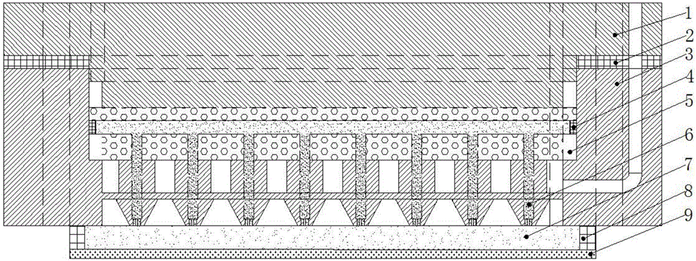
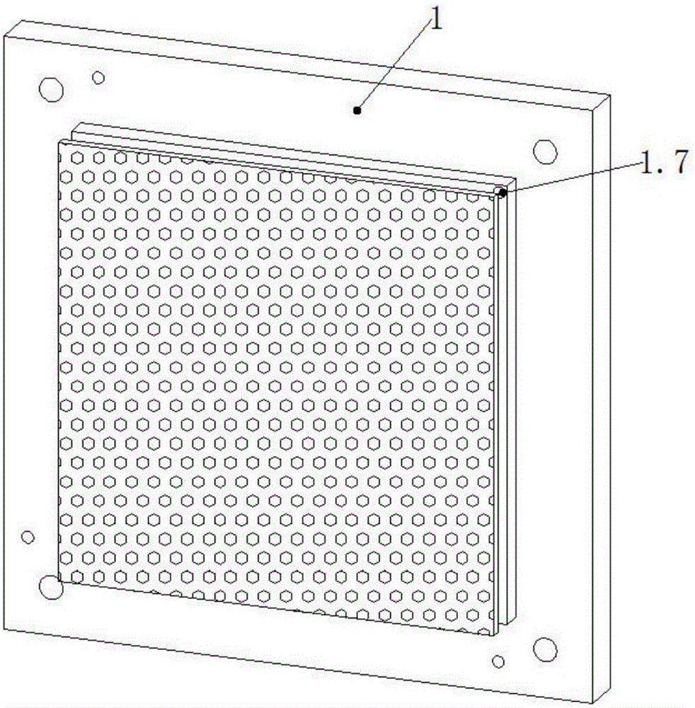
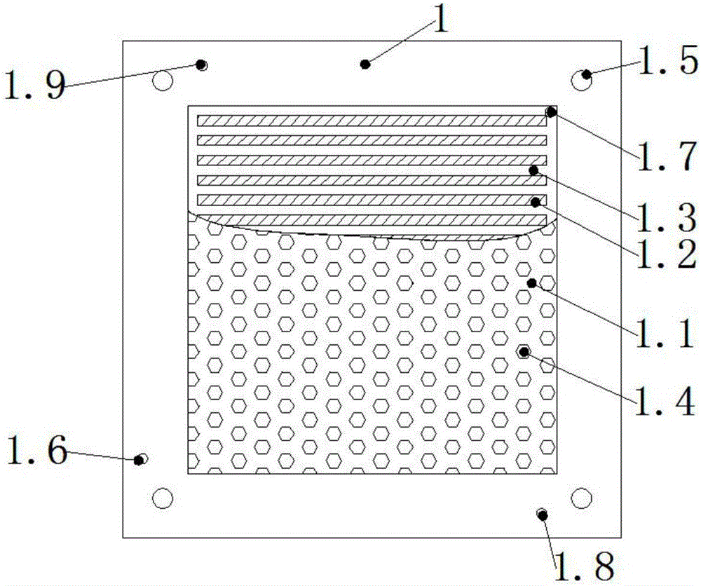
[0033] Such as figure 1 The flow field plate structure shown to improve the drainage performance of the fuel cell includes a flow field plate 3, an upper support layer 1, a liquid-absorbing material 6, a gas diffusion layer 7 and a catalytic layer 9, which are arranged on the top of the flow field plate 3 Supporting layer 1, the edge of the bottom surface of the upper supporting layer 1 is connected to the edge of the top surface of the flow field plate 3 (it can be connected by bolts, and bolt holes are correspondingly opened on the upper supporting layer 1 and the flow field plate 3), the connecting surface of the two An outer gasket 2 for sealing is arranged on the top; a hollow layer 1.1 is provided in the middle of the bottom surface of the upper support layer 1, and the hollow layer 1.1...


PUM


Abstract

The invention provides a flow field plate structure for increasing drainage performance of a fuel cell, wherein the flow field plate structure comprises a flow field plate, an upper support layer, a liquid absorbing material, a gas diffusion layer and a catalytic layer; the top of the flow field plate is provided with the upper support layer, and the edge of the bottom face of the upper support layer is connected with the edge of the top face of the flow field plate; the middle of the bottom face of the upper support layer is provided with a hollow-out layer; the bottom of the flow field plate is provided with the gas diffusion layer and the catalytic layer from top to bottom; the liquid absorbing material is arranged vertically, the lower part of the liquid absorbing material makes contact with the gas diffusion layer, and the upper part of the liquid absorbing material passes through the flow field plate and is connected with the upper support layer; the upper support layer and the flow field plate are respectively provided with dry gas inlets, reaction gas inlets and reaction gas outlets which communicate correspondingly, the upper support layer is provided with a dry gas outlet, and the dry gas inlets communicate with the liquid absorbing material. The flow field plate structure has the advantages that the flow field plate structure is provided with dry gas flow channels alone, dry gas is used for achieving transpiration of the liquid absorbing material, and flow of the dry gas of the fuel cell and flow of reaction gas of the fuel cell are not interfered with each other.

Description

technical field [0001] The invention relates to the technical field of fuel cells, in particular to a flow field plate structure for improving the drainage performance of fuel cells. Background technique [0002] The water management and temperature problems of fuel cells have always been the main factors that plague their performance improvement. When the fuel cell stack works at a high current density, it is prone to "water flooding" and overheating in the battery, which seriously affects performance of the fuel cell. Therefore, it is necessary to adopt a reasonable method to improve the water management problem in the fuel cell and to cool the battery so as to improve the working performance of the fuel cell. At present, there are many designs of different flow field plate flow channel structures and improved materials in the battery. Although these methods have alleviated the degree of "water flooding" and excessive temperature in the battery to a certain extent, they a...

Claims


Application Information

Patent Timeline
Patent Type & Authority Applications(China)
IPC IPC(8): H01M8/0258H01M8/0267H01M8/04119
CPCH01M8/0258H01M8/0267H01M8/04156H01M8/04171Y02E60/50
Inventor 陈涛刘士华陈见易伟张恒刘树良叶梦力邓炎
Owner WUHAN UNIV OF TECH
Why Eureka
Try Eureka