Pressure control equipment for fuel cell

A fuel cell and equipment technology, applied in the direction of fuel cell control, fuel cells, fuel cell additives, etc., can solve problems affecting battery use and output power, inconsistency, and increased air pressure fluctuations, etc., to achieve reasonable and effective use of space , Improve humidification efficiency and control speed

Active Publication Date: 2017-05-24
DEYANG JIUDING ZHIYUAN INTPROP OPERATION CO LTD
View PDF6 Cites 2 Cited by
  • Summary
  • Abstract
  • Description
  • Claims
  • Application Information

AI Technical Summary

Problems solved by technology

Since the hydrogen and oxygen in the fuel cell must be fully humidified and maintained at pressure, if the pressure or humidity is not enough, it will easily cause fuel waste and indiscriminate combustion, which will affect the use and output power of the battery
[0003] When the existing hydrogen fuel cell is used, it is often necessary to adjust the air pressure, temperature

Method used


Image

  • Pressure control equipment for fuel cell
  • Pressure control equipment for fuel cell
  • Pressure control equipment for fuel cell

Examples


Embodiment 2

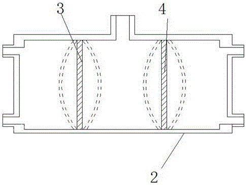
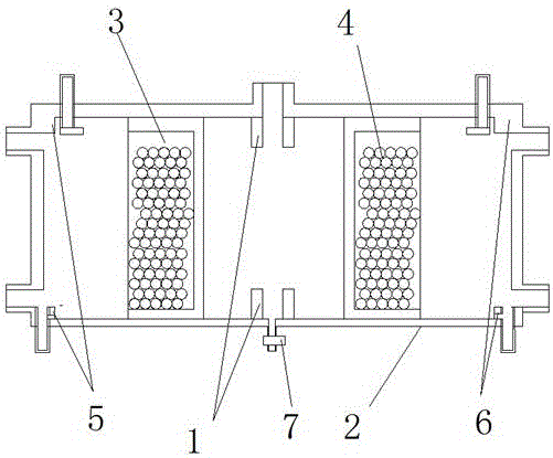
[0030] like figure 2 As shown, the present invention discloses a pressure control device for a fuel cell, comprising a tubular casing 2, which can be provided with a first isolation part 3 and a second isolation part 4, and the casing 2 is divided into a gas cavity, a The air cavity and the pressure regulating cavity, the gas cavity and the pressure regulating cavity are sealed and isolated by the movable first isolation part 3, and the air cavity and the pressure regulating cavity are sealed and isolated by the movable second isolation part 4; the gas cavity is used to communicate with the gas source, and the air The cavity is used to communicate with the air source, and the pressure regulating cavity is used to communicate with the inflation and deflation device. The first isolation part 3 and the second isolation part 4 are piston-shaped; the piston can slide along the side wall of the pipe body, and the two sides of the piston are respectively provided with limit parts so...

Embodiment 3

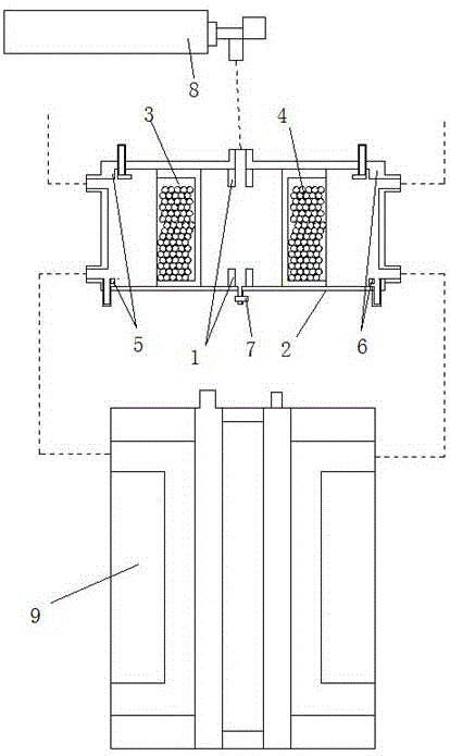
[0034] like image 3 As shown, based on the pressure control device in Example 1, its method for hydrogen fuel cell 9:

[0035] Step 1: The MCU controls the spray pump to output water flow at a speed of 0.8-1.2L / min. The water mist nozzle is in the shape of a flat fan to spray the water mist to the glass beads. The MCU controls the heating lamp to heat the gas cavity and the air cavity. The speed of 10-16m / s is sprayed into the humidity control chamber and humidified to the saturated humidity at the gap between the glass beads. Heating to 80-85℃, then output from the gas outlet / air outlet; the volume ratio of gas flow and water flow in the gas cavity and air cavity is 15-20:1;

[0036] Step 2: The pressure difference between the gas chamber and the pressure regulating chamber controls the movement of the first isolation part 3, and the pressure difference between the pressure regulating chamber and the air chamber controls the movement of the second isolation part 4, so that ...


PUM


Abstract

The invention relates to pressure control equipment for a fuel cell, and belongs to the field of associated equipment of a fuel cell, in particular to auxiliary pressure balance equipment for a fuel cell used in the field of new energy automobiles. The pressure control equipment comprises a tubular shell, wherein a first isolation part and a second isolation part are arranged in the shell; the inside of the shell is partitioned into a fuel gas cavity, an air cavity and a pressure-regulating cavity; the fuel gas cavity and the pressure-regulating cavity are sealed and isolated through the movable first isolation part; the air cavity and the pressure-regulating cavity are sealed and isolated through the movable second isolation part; the fuel gas cavity is used for communicating with a fuel gas source; the air cavity is used for communicating with an air source; the pressure-regulating cavity is used for communicating with an inflating and deflating device. In the structure, the pressure difference between the fuel gas cavity and the air cavity can be balanced in real time through the principle that the first isolation part and the second isolation part can move under the pressure difference; moreover, the air pressures in the fuel gas cavity and the air cavity can be regulated to a required air pressure range in real time through the pressure-regulating cavity; the pressure-regulating cavity is connected to the two sides of the fuel cell, so that pressure keeping and pressure balancing in the fuel cell are realized.

Description

technical field [0001] The invention relates to a pressure control device for a fuel cell, belonging to the field of supporting equipment for the fuel cell, in particular to a device for providing auxiliary pressure equalization for the fuel cell used in the field of new energy vehicles. Background technique [0002] Fuel cells are widely used, not only in the fields of military, space, power plants, but also in motor vehicles, mobile devices, and households. Early fuel cell development focused on specialized applications such as military space and distributed power generation above the kilowatt level. The field of electric vehicles has become the main direction of the application of fuel cells, and a variety of automatic vehicles that use fuel cells to generate electricity have appeared in the market. In addition, the application of fuel cells to general consumer electronic products through miniaturized technology is also one of the application development directions. With...

Claims


Application Information

Patent Timeline
IPC IPC(8): H01M8/04H01M8/04298H01M8/04746
CPCH01M8/04H01M8/04298H01M8/04746Y02E60/50
Inventor 陈福彦
Owner DEYANG JIUDING ZHIYUAN INTPROP OPERATION CO LTD
Why Eureka
Try Eureka