Sound cavity structure and mobile terminal

A sound cavity and front cavity technology, applied in the field of sound cavity structure and mobile terminals, can solve the problems of long mold manufacturing cycle, large workload, and cumbersome manual work, so as to reduce the production cost, ensure the sealing performance, and ensure the sealing stability. Effect

Active Publication Date: 2017-05-24
NUBIA TECHNOLOGY CO LTD
View PDF5 Cites 13 Cited by
  • Summary
  • Abstract
  • Description
  • Claims
  • Application Information

AI Technical Summary

Problems solved by technology

In the application of the box integrated sound cavity mentioned above, the mobile phone shell and the box are mostly connected by screws, and the rear shell is connected with the box sound cavity by screws and is set as an integrated structure; the installation process of each component of the box and the rear shell is manual. cumbersome and heavy workload
[0003] In addition, the above-mentioned box integrated sound cavity needs to customize a special mold, the cost of the above-mentioned special mold is high and the mold manufacturing cycle is long; at the same time, the front sound cavity of the BOX integrated sound cavity and the shell need to be sealed by foam. Easy to cause sealing problems

Method used


Image

  • Sound cavity structure and mobile terminal
  • Sound cavity structure and mobile terminal
  • Sound cavity structure and mobile terminal

Examples


Embodiment 1

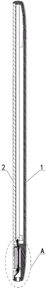
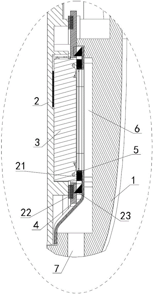
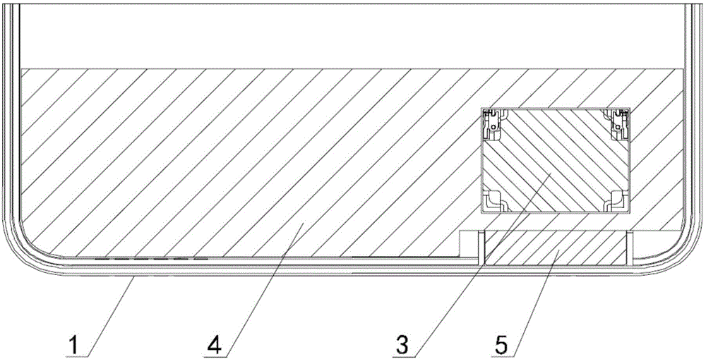
[0045] combine Figure 1-Figure 6 As shown, a sound chamber structure provided in Embodiment 1 of the present invention may include: a housing and a circuit board 4, a speaker 3, and a support plate 5 disposed inside the housing; the housing includes a first housing 1, The second housing 2 and the loudspeaker 3 are installed on the circuit board 4; wherein, the first housing 1 is provided with a sound outlet hole 7 passing through the first housing 1, and the inner side of the first housing 1 is provided with the sound outlet hole 7. The front chamber channel 6; the inner side of the second housing 2 is provided with a groove for accommodating the speaker 3; in specific operation, the above-mentioned speaker 3 can be installed on the circuit board 4, and the basic circuit connection of the speaker 3 can be completed.

[0046] Further, the support plate 5 has a hollow channel, one side of the support plate 5 is the first side 52 connected to the outer edge of the port of the fr...

Embodiment 2

[0060] The substantial difference between the second embodiment and the first embodiment is that: a first positioning structure is also provided;

[0061] combine Figure 7 As shown, the sound chamber structure provided in the second embodiment of the present invention has a main structure similar to that of the first embodiment, and also includes: a housing and a circuit board 4, a speaker, and a support plate arranged inside the housing; the housing includes interconnected The first shell 1, the second shell, and the speaker are installed on the circuit board 4; the first shell 1 is provided with a sound hole that runs through the first shell 1, and the inside of the first shell 1 is provided with a sound hole that communicates with the sound hole. The front chamber channel; the inner side of the second housing is provided with a groove for accommodating the loudspeaker; the support plate has a hollow channel, one side of the support plate is the first side connected to the ...

Embodiment 3

[0067] The substantial difference between the third embodiment and the first embodiment is that: there is also a second positioning structure;

[0068] In the sound chamber structure provided in the third embodiment of the present invention, the main structure is similar to that of the first embodiment. For the sealing form of the cavity and the rear sound cavity, and the assembly operation of the sound cavity structure, please refer to the records in the first embodiment above. The third embodiment aims to illustrate the specific setting of the second positioning structure.

[0069] In this embodiment, a second positioning structure is provided between the above-mentioned circuit board and the speaker; through the setting of the above-mentioned second positioning structure, the convenient assembly operation and precise installation operation of the speaker and the circuit board can be effectively guaranteed; Poor contact caused by errors can effectively ensure the overall rel...


PUM


Abstract

The invention discloses a sound cavity structure and a mobile terminal. The sound cavity structure comprises a shell and a circuit board, a loudspeaker and a supporting plate which are arranged in the shell. The shell comprises a first shell body and a second shell body which are mutually connected. The first shell body is provided with a sound outlet hole penetrating through the first shell body. The internal side of the first shell body is provided with a front cavity channel communicated with the sound outlet hole. The internal side of the second shell body is provided with a slot body used for accommodating the loudspeaker. The mobile terminal comprises the sound cavity structure and a display screen. The display screen is installed at the external side of the second shell body. The sound cavity structure can be applied to the technical field of communication electronics, the defects in the prior art can be effectively overcome by applying the sound cavity structure, an independent application of the integrated BOX can be replaced by the optimized connection arrangement of the component, the limitation caused by the mould manufacturing period and the manufacturing cost of the integrated BOX can be eliminated, the concrete composition of the sound cavity structure can be optimized, the sealing problem caused by the integrated BOX can be avoided and the overall sealing performance of the structure can be enhanced.

Description

technical field [0001] The invention relates to the technical field of communication electronics, in particular to a sound chamber structure and a mobile terminal. Background technique [0002] At present, on smartphones, the integrated box design scheme that seals the speaker separately in a closed sound cavity is becoming more and more popular; among them, the speaker side sound output method mainly adopts the integrated BOX method. In the application of the box integrated sound cavity mentioned above, the mobile phone shell and the box are mostly connected by screws, and the rear shell is connected with the box sound cavity by screws and is set as an integrated structure; the installation process of each component of the box and the rear shell is manual. It is cumbersome and the workload is heavy. [0003] In addition, the above-mentioned box integrated sound cavity needs to customize a special mold, the cost of the above-mentioned special mold is high and the mold manuf...

Claims


Application Information

Patent Timeline
Patent Type & Authority Applications(China)
IPC IPC(8): H04R9/06H04R9/02H04M1/03
Inventor 罗富兵
Owner NUBIA TECHNOLOGY CO LTD
Why Eureka
Try Eureka