Back plate multi-channel electrostatic transducer

A multi-channel, electrostatic technology, used in electrostatic sensors, sensors, electrical components, etc., can solve the problems of inability to meet high-end places, uncontrollable sound wave direction, and sound wave no directivity.

Active Publication Date: 2019-04-19
AUDFLY TECH SUZHOU CO LTD
View PDF8 Cites 0 Cited by
  • Summary
  • Abstract
  • Description
  • Claims
  • Application Information

AI Technical Summary

Problems solved by technology

[0003] However, the existing electrostatic transducer, such as the patent number is 201280035607.2, and the patent name is electrostatic transducer, the direction of the sound wave emitted by the transducer is uncontrollable, the sound wave has no directivity, and cannot meet the needs of high-end places

Method used


Image

  • Back plate multi-channel electrostatic transducer
  • Back plate multi-channel electrostatic transducer

Examples


Embodiment 1

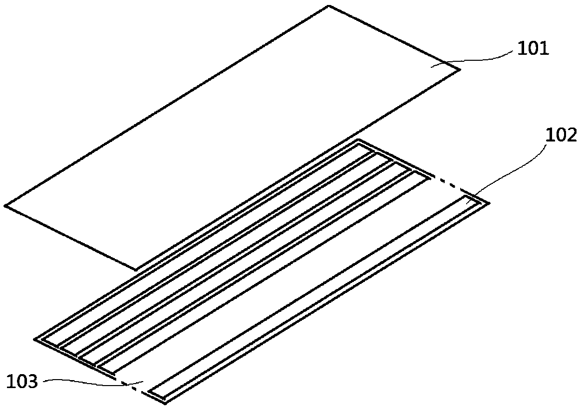
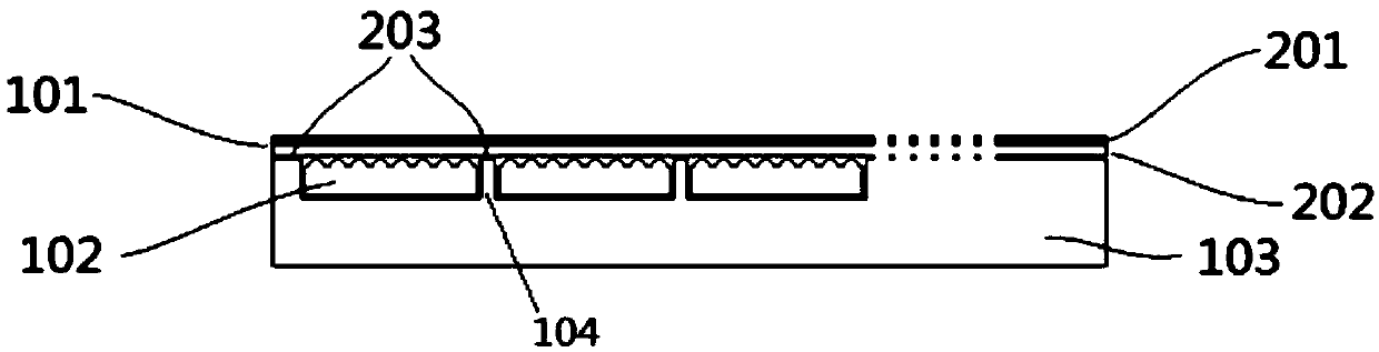
[0029] The present invention provides a multi-channel electrostatic transducer with a back plate, such as Figure 1-2 As shown, it includes a first layer 103 with a certain thickness and a second layer 101 disposed on the first layer 103. The first layer 103 is an insulating layer, which may be an insulating polymer material. The surface of the first layer 103 is spaced apart from a plurality of Channels, in this embodiment, the channels are equally spaced along the length direction of the first layer 103 on the surface of the first layer 103, and each channel is arranged in parallel to form a frame array evenly arranged on the first layer 103, and the frame array around the frame array One layer 103 is provided with a reserved area, and a spacer layer 104 is formed between two adjacent channels to insulate each channel from each other. The width of the spacer layer 104 is preferably 0.5 mm.

[0030] Each channel is provided with a back electrode plate 102, thereby forming a m...

Embodiment 2

[0037]The difference from Embodiment 1 lies in the connection method between the first layer 103 and the flexible insulating layer 202. A flexible adhesive 203 is provided on the upper end of each spacer layer 104. The adhesive 203 is a continuous layer extending along the upper end of the spacer layer 104. Either in the form of intermittent tape / water, or discrete adhesive sheets spaced a certain distance along the spacer layer 104 . In this embodiment, the adhesive 203 is in the form of continuous glue, the adhesive 203 is spread over the upper end of the spacer layer 104 along the length direction of the spacer layer 104, and the main body area between the first layer 103 and the flexible insulating layer 202 is glued. The mixture 203 is combined so that the adhesive 203 adheres to the two layers, and the flexible insulating layer 202 is fixed on the first layer 103 along the position of the adhesive 203, so that each back electrode plate 102 The upper end forms an independ...

Embodiment 3

[0039] The difference from Embodiment 1 lies in the connection mode between the first layer 103 and the flexible insulating layer 202, and the flexible insulating layer 202 at the corresponding position on the upper end of each spacer layer 104 is welded in a continuous or discontinuous manner along the upper end of the spacer layer 104. The upper end of each spacer layer 104 is welded to the upper end of each spacer layer 104 at a certain distance along the spacer layer 104, so that the first layer 103 and the flexible insulating layer 202 are fixed, and the flexible insulating layer 202 is in a tight state. In this embodiment, the welding points 203 are intermittently welded. The welding points 203 are intermittently distributed on the upper end of the spacer layer 104 along the length direction of the spacer layer 104. The main body area between the first layer 103 and the flexible insulating layer 202 Bonded together by welding points 203, so that the welding points 203 adh...


PUM


Abstract

The present invention discloses a back plate multi-channel electrostatic transducer. The transducer comprises a first layer, a back electrode plate, and a second layer. The first layer is an insulating layer, and at least two channels are disposed on the surface of the first layer at intervals. The back electrode plate is disposed in the channels. The second layer comprises a flexible insulating layer disposed on the first layer and a flexible conductive layer disposed on the flexible insulating layer. The first layer and the flexible insulating layer are separated. The flexible insulating layer is combined with the first layer along a string of contact parts isolated on the first layer. The back plate is provided with multiple channels of electrode plate, a vibration diagram at the upper end of each electrode plate vibrates independently and can load audio or supersonic signals, a sound wave radiation direction is controlled through adjusting amplitudes and phases of different channels, so that the transducer is directed, the sound wave can track a dynamic target so as to meet the use requirement of a high-end site, side lobe effect is eliminated, sound quality is improved, and noise and loss are reduced.

Description

technical field [0001] The invention relates to the technical field of transducers, and more specifically, the invention relates to a multi-channel electrostatic transducer with a back plate. Background technique [0002] A conventional electrostatic transducer consists of a conductive film disposed between conductive back plates to form a capacitor, a DC bias is applied to the film, and an AC signal voltage is applied to the conductive back plates. A voltage of hundreds or even thousands of volts applied to the conductive backplate exerts a force on the charged membrane, which moves thereby driving the air on either side of it. [0003] But the existing electrostatic transducer, such as the patent number is 201280035607.2, and the patent name is an electrostatic transducer, the direction of the sound wave emitted by the transducer is uncontrollable, the sound wave has no directivity, and cannot meet the needs of high-end places. Contents of the invention [0004] It is a...

Claims


Application Information

Patent Timeline
Patent Type & Authority Patents(China)
IPC IPC(8): H04R19/00
CPCH04R19/00
Inventor 栗振
Owner AUDFLY TECH SUZHOU CO LTD
Why Eureka
Try Eureka