Back plate multi-channel electrostatic transducer
A multi-channel, electrostatic technology, used in electrostatic sensors, sensors, electrical components, etc., can solve the problems of no directivity of sound waves, uncontrollable sound wave directions, and inability to meet high-end places.
- Summary
- Abstract
- Description
- Claims
- Application Information
AI Technical Summary
Problems solved by technology
Method used
Image
Examples
Embodiment 1
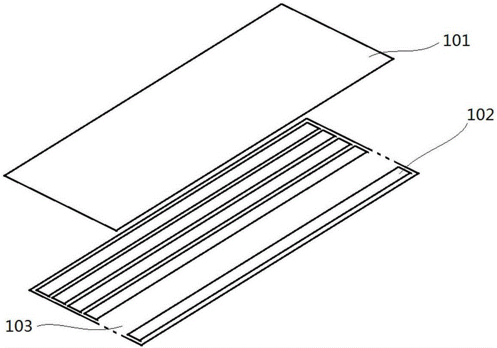
[0029] The present invention provides a multi-channel electrostatic transducer with a back plate, such as Figure 1-2 As shown, it includes a first layer 103 with a certain thickness and a second layer 101 disposed on the first layer 103. The first layer 103 is an insulating layer, which may be an insulating polymer material. The surface of the first layer 103 is spaced apart from a plurality of Channels, in this embodiment, the channels are equally spaced along the length direction of the first layer 103 on the surface of the first layer 103, and each channel is arranged in parallel to form a frame array evenly arranged on the first layer 103, and the frame array around the frame array One layer 103 is provided with a reserved area, and a spacer layer 104 is formed between two adjacent channels to insulate each channel from each other. The width of the spacer layer 104 is preferably 0.5 mm.
[0030] Each channel is provided with a back electrode plate 102, thereby forming a m...
Embodiment 2
[0037]The difference from Embodiment 1 lies in the connection method between the first layer 103 and the flexible insulating layer 202. A flexible adhesive 203 is provided on the upper end of each spacer layer 104. The adhesive 203 is a continuous layer extending along the upper end of the spacer layer 104. Either in the form of intermittent tape / water, or discrete adhesive sheets spaced a certain distance along the spacer layer 104 . In this embodiment, the adhesive 203 is in the form of continuous glue, the adhesive 203 is spread over the upper end of the spacer layer 104 along the length direction of the spacer layer 104, and the main body area between the first layer 103 and the flexible insulating layer 202 is glued. The mixture 203 is combined so that the adhesive 203 adheres to the two layers, and the flexible insulating layer 202 is fixed on the first layer 103 along the position of the adhesive 203, so that each back electrode plate 102 The upper end forms an independ...
Embodiment 3
[0039] The difference from Embodiment 1 lies in the connection mode between the first layer 103 and the flexible insulating layer 202, and the flexible insulating layer 202 at the corresponding position on the upper end of each spacer layer 104 is welded in a continuous or discontinuous manner along the upper end of the spacer layer 104. The upper end of each spacer layer 104 is welded to the upper end of each spacer layer 104 at a certain distance along the spacer layer 104, so that the first layer 103 and the flexible insulating layer 202 are fixed, and the flexible insulating layer 202 is in a tight state. In this embodiment, the welding points 203 are intermittently welded. The welding points 203 are intermittently distributed on the upper end of the spacer layer 104 along the length direction of the spacer layer 104. The main body area between the first layer 103 and the flexible insulating layer 202 Bonded together by welding points 203, so that the welding points 203 adh...
PUM
 Abstract
Description
Claims
Application Information
 - R&D
- Intellectual Property
- Life Sciences
- Materials
- Tech Scout
- Unparalleled Data Quality
- Higher Quality Content
- 60% Fewer Hallucinations
Browse by: Latest US Patents, China's latest patents, Technical Efficacy Thesaurus, Application Domain, Technology Topic, Popular Technical Reports.
© 2025 PatSnap. All rights reserved.Legal|Privacy policy|Modern Slavery Act Transparency Statement|Sitemap|About US| Contact US: help@patsnap.com


