
System and method for modulating laser pulses

A technology for modulating lasers and laser pulses, applied in lasers, laser welding equipment, laser parts, etc., it can solve problems such as damage to processing results, incorrect modulation of laser pulses, etc., to achieve short rise or switching time, small switching loss, reduction of The effect of arcing danger

Active Publication Date: 2017-05-24
AMPHOS
View PDF5 Cites 2 Cited by
  • Summary
  • Abstract
  • Description
  • Claims
  • Application Information

AI Technical Summary

Problems solved by technology

Because the rise time lasts too long, incorrect modulation of individual or multiple laser pulses can result, which can lead to undesired damage to the processing result, for example in material processing

Method used


Image

  • System and method for modulating laser pulses
  • System and method for modulating laser pulses
  • System and method for modulating laser pulses

Examples


Embodiment Construction

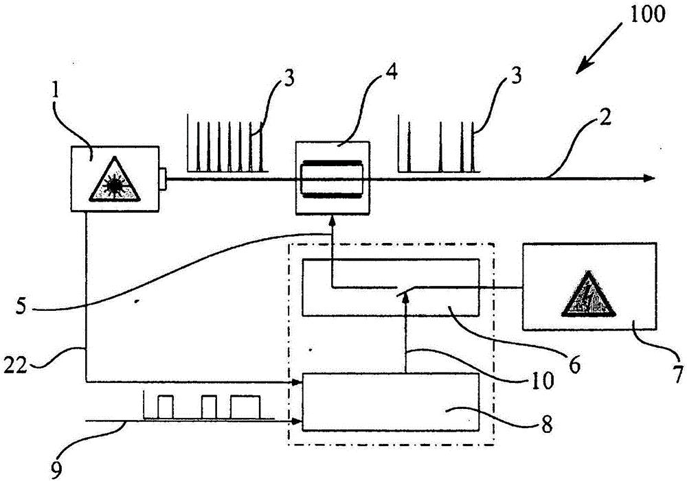
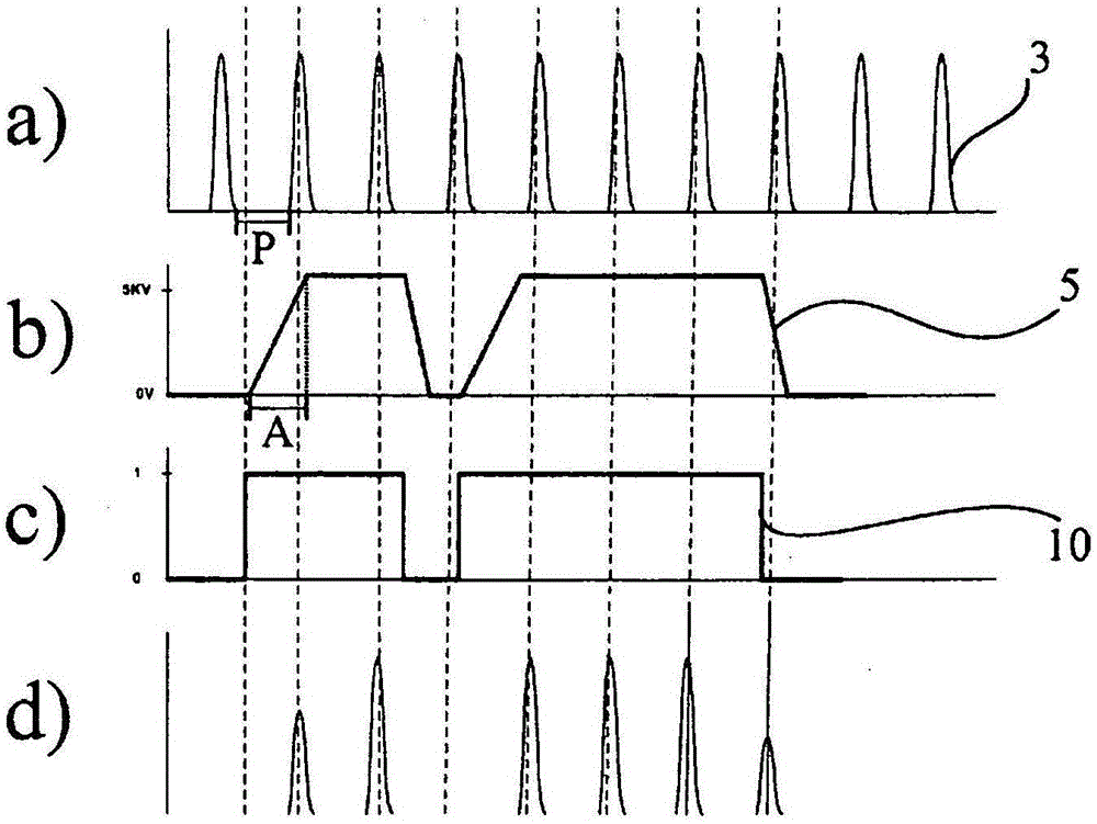
[0041] First, then with the help of Figures 3 to 8 Before discussing the details of the device 100 according to the present invention, the views in figure 1 and 2 The views in discuss the device 100 known from the prior art and the disadvantages associated therewith.

[0042] figure 1 Shown is the structure known from the prior art of a device 100 with a laser 1 and an electro-optical modulator 4 connected downstream of the laser 1, which is to be modulated by the laser according to a specific modulation preset value 1 produces a pulsed laser beam 2. Such a device 100 is generally used in material processing, but also in measurement technology or in principle research. The pulsed laser beam 2 must therefore be modulated in accordance with the respective requirements of the application, wherein the individual pulses 3 generally need to be modulated in a targeted manner.

[0043] Depending on the application for which the pulsed laser beam 2 is to be used, it is necessary ...


PUM


Abstract

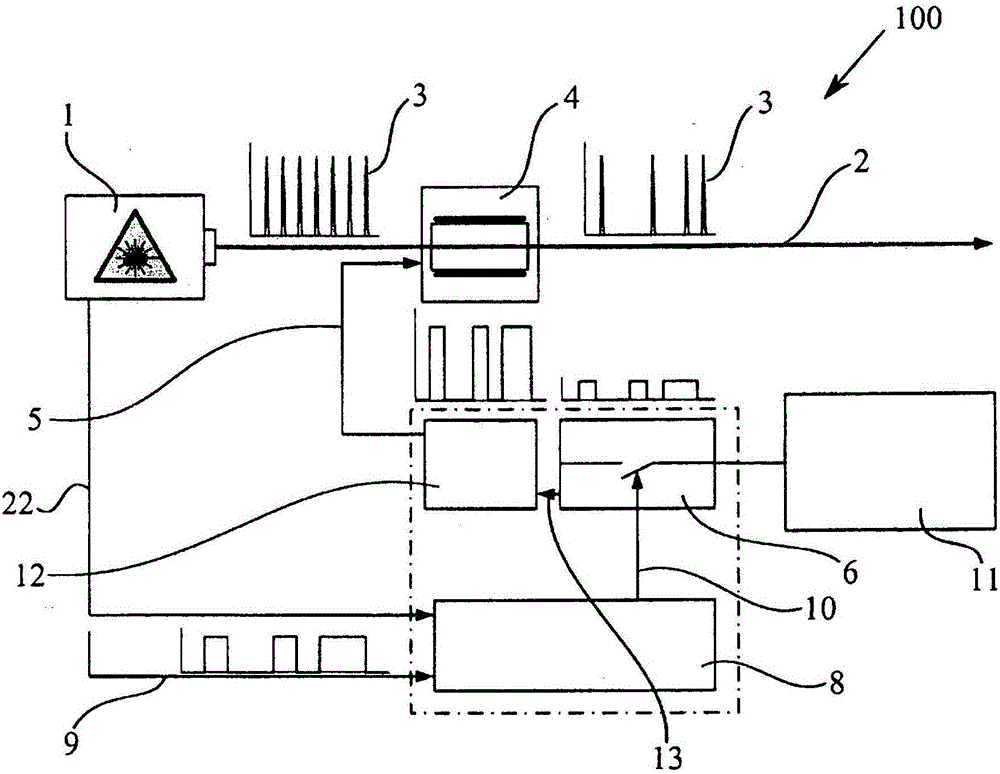
The present invention relates to a system for modulating laser pulses (3) by means of an electro-optical modulator (4) which is operated by means of a pulsed modulation voltage (5). A voltage converter (12) mounted upstream of the modulator (4) converts a pulsed modulated switching voltage (13) at an output voltage level to the modulation voltage (5) that is higher than the output voltage level. The invention further relates to a method for modulating laser pulses (3).

Description

technical field [0001] The invention relates to a device and a method for modulating laser pulses by means of an electro-optical modulator, which is operated by the modulation voltage of the pulses. Background technique [0002] Devices of this type and corresponding methods are mainly used industrially in the field of material processing by means of laser radiation, for example in the area of ​​stripping or conditioning processes in the printing industry, in perforating films or other processes . But it is also applied differently in measurement technology and theoretical research. In this case, a pulsed laser beam is provided by the laser, the individual pulses of which must be modulated according to the requirements of the respective application. [0003] Depending on the application for which the laser is used, it may be required that the intensity of one or more laser pulses must be changed. It is also possible that only certain laser pulses should be diverted from t...

Claims


Application Information

Patent Timeline
Patent Type & Authority Applications(China)
IPC IPC(8): H01S3/00
CPCH01S3/0085B23K26/0624B23K26/0622H01S3/11H01S5/0085H01S3/107
Inventor J·多尔克迈尔C·施尼茨勒T·曼斯S·费尔泽M·黑辛J·马丁尼
Owner AMPHOS
Learn More