
Blood pressure measuring device

A blood pressure measurement device and the technology of the measurement device, which are applied in the field of medical equipment, can solve problems such as weak sound sensitivity, different oscillatory wave signal strengths, unfavorable systolic blood pressure measurement, etc., and achieve the effect of facilitating judgment and improving signal detection sensitivity

Active Publication Date: 2017-05-31
广东润池科技有限公司
View PDF6 Cites 8 Cited by
  • Summary
  • Abstract
  • Description
  • Claims
  • Application Information

AI Technical Summary

Problems solved by technology

[0003] However, blood pressure measurement by auscultation needs to be operated by trained professional medical personnel, which is not conducive to self-measurement of blood pressure by users at home; and this method cannot adapt to the measurement and monitoring of ambulatory blood pressure; at the same time, the accuracy of blood pressure measurement is easily affected. The influence of ambient sound
The electronic method, which uses a microphone instead of a stethoscope, is also easily affected by ambient sounds, and the sensitivity of detecting sound in the cuff is weaker than that of the oscillometric method
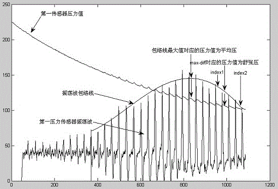
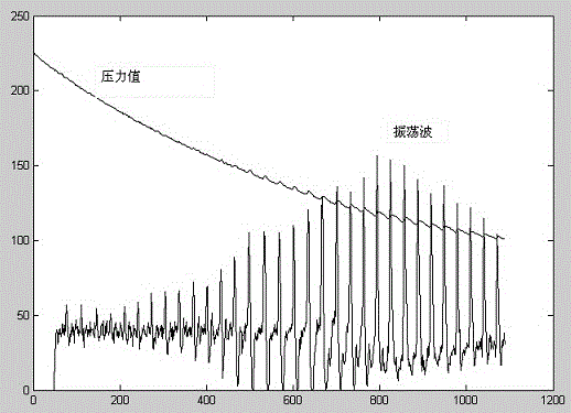
[0004] For the oscillometric blood pressure measurement of a single balloon, compared with the auscultation method, the sensitivity of detecting the oscillating wave in the cuff is stronger, and it is not easily affected by the surrounding noise. However, there are still the following problems: (1) Due to the impact of the blood flow at the proximal end of the cuff, before the blood flow of the limb arteries is opened, an oscillation wave of a certain size can also be detected in the cuff (see appendix figure 2 , the pressure value and oscillation wave during the deflation process of a single balloon in a normal person), and as the pressure decreases, it also shows a trend of increasing gradually, so the pressure in the cuff is lower than the systolic pressure of the human body, and the arterial blood flow is reopened At the moment, the oscillating wave signal detected in the cuff has no clear sign, which is not conducive to the measurement of systolic blood pressure; (2) Due to the above reasons (1), the blood pressure measurement using the oscillometric method is generally the amplitude coefficient method, and the systolic blood pressure The magnitude coefficients of blood pressure and diastolic blood pressure are based on big data statistics, so there are certain individual differences, and there will be a large gap between the real blood pressure and the real blood pressure when measured by some users; (3) For patients with frequent premature beats or Arrhythmia patients with atrial fibrillation, because the strength of each heart pumping is different, the strength of the oscillatory wave signal generated in each stroke in the cuff is also different (see appendix image 3 , the pressure value and oscillation wave during the deflation process of a single balloon in patients with atrial fibrillation; attached Figure 4 , the pressure value and oscillation wave during the deflation process of the single balloon with frequent premature beats), so it does not strictly conform to the process that the detected oscillation wave signal changes from small to large during the deflation process, and then decreases to a certain extent after increasing to a certain extent. Lead to large errors in blood pressure measurement in patients with frequent premature beats or atrial fibrillation
[0005] The prior art has not yet solved how to accurately locate the pressure in the cuff corresponding to the moment when the measured arterial blood pressure occurs, especially for arrhythmia patients with atrial fibrillation

Method used


Image

  • Blood pressure measuring device
  • Blood pressure measuring device
  • Blood pressure measuring device

Examples


Embodiment Construction

[0037] The present invention will be further described below in conjunction with the accompanying drawings. The following examples are only used to illustrate the technical solution of the present invention more clearly, but not to limit the protection scope of the present invention.

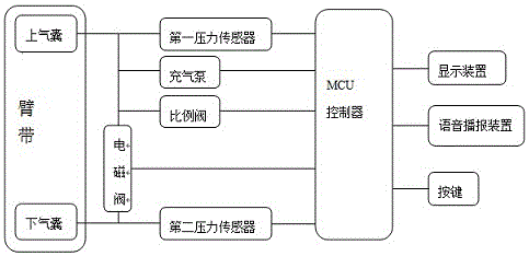
[0038] Such as figure 1 As shown, a blood pressure measuring device of the present invention consists of double airbag cuffs, double pressure sensors, an air pump, a proportional deflation valve, a solenoid valve and an MCU controller, a measurement result display device, a voice broadcast device, and buttons It consists of a control line connecting the air pump, a solenoid valve and a proportional deflation valve, and a number of signal lines connecting the pressure sensor respectively.

[0039] The measuring device inflates the two airbags in the cuff through an air pump; the dual pressure sensors respectively detect the pressure value and oscillation wave in the upstream and downstream airb...


PUM


Abstract

The invention discloses a blood pressure measuring device. The blood pressure measuring device is formed by double airbag sleeve belts, double pressure sensors, an air pump, a proportion deflation valve, a solenoid valve, an MCU controller, a measurement result display device, a voice broadcast device, and a button. The blood pressure measuring device is provided with a control circuit connected with the air pump, the solenoid valve and the proportion deflation valve, and a plurality of signal circuits respectively connected with the pressure sensors. The blood pressure measuring device uses two pressure sensors. A microphone is avoided from affecting by the surrounding noise while the signal detection sensitivity is improved. The data collection of two pressure sensors is synchronous in the timing sequence. According to an oscillatory wave signal of the second pressure sensor detected by the downstream airbag, the pressure value detected by the first pressure sensor in the upstream airbag is judged while the artery blood flow is opened, so that the systolic pressure of the detected artery is determined.

Description

technical field [0001] The invention relates to the technical field of medical instruments, in particular to a blood pressure measuring device. Background technique [0002] Non-invasive blood pressure measurement methods mainly include auscultation, oscillometric method, and the method of using a microphone instead of a stethoscope, but they are all based on an inflatable airbag cuff. In the process of reopening the blocked arterial blood flow, the Korotkoff sound or pulse oscillation signal in the cuff is detected to realize the measurement of systolic blood pressure, diastolic blood pressure, mean pressure and pulse rate. [0003] However, blood pressure measurement by auscultation needs to be operated by trained professional medical personnel, which is not conducive to self-measurement of blood pressure by users at home; and this method cannot adapt to the measurement and monitoring of ambulatory blood pressure; at the same time, the accuracy of blood pressure measuremen...

Claims


Application Information

Patent Timeline
IPC IPC(8): A61B5/0225A61B5/0235
CPCA61B5/02116A61B5/02141A61B5/0225A61B5/0235A61B5/024A61B5/72A61B5/7405
Inventor 林进榕
Owner 广东润池科技有限公司
Learn More