Ultraviolet photo-catalytic oxidation device
A technology of photocatalytic oxidation and ultraviolet light, applied in chemical instruments and methods, gas treatment, membrane technology, etc., can solve the problems of low photocatalytic efficiency of ultraviolet light, high equipment cost, dispersion of ultraviolet light, etc., and improve the efficiency of catalytic degradation , Improve the reflection effect and reduce the cost
- Summary
- Abstract
- Description
- Claims
- Application Information
AI Technical Summary
Problems solved by technology
Method used
Image

Examples
Embodiment 1
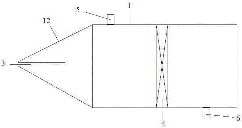
[0034] Such as figure 1 As shown, a kind of ultraviolet light photocatalytic oxidation device comprises reactor 1, and one end of described reactor 1 is connected with reflector 12, and the inner surface of described reflector 12 is provided with ultraviolet light reflective coating, and described reflector 12 2 is connected with a first ultraviolet lamp 3, the inner wall of the reactor 1 is connected with a photocatalytic oxidation layer 4, and the side of the reactor 1 connected with the reflector 12 is provided with an air inlet 5, and the A gas outlet 6 is opened on the other side of the reactor, and the photocatalytic oxidation layer 4 is located between the gas inlet 5 and the gas outlet 6 .
[0035] The number of layers of the photocatalytic oxidation layer 4 is one.
[0036] The shape of the reflector 12 is set as a hollow cone.
[0037] The apex angle of the air cone is 30° to 120°, preferably 60°.
[0038] The material of the ultraviolet reflective coating is pref...
Embodiment 2
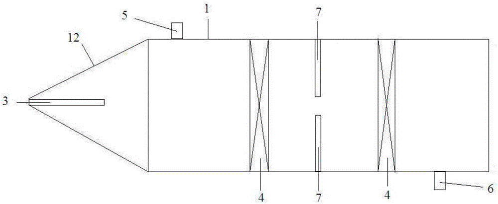
[0041] Such as figure 2 As shown, a kind of ultraviolet light photocatalytic oxidation device comprises reactor 1, and one end of described reactor 1 is connected with reflector 12, and the inner surface of described reflector 12 is provided with ultraviolet light reflective coating, and described reflector 12 2 is connected with a first ultraviolet lamp 3, the inner wall of the reactor 1 is connected with a photocatalytic oxidation layer 4, and the side of the reactor 1 connected with the reflector 12 is provided with an air inlet 5, and the A gas outlet 6 is opened on the other side of the reactor, and the photocatalytic oxidation layer 4 is located between the gas inlet 5 and the gas outlet 6 .
[0042] The number of layers of the photocatalytic oxidation layer 4 is N, wherein N is an integer greater than or equal to 2, preferably 2. The inner wall of the reactor 1 is connected with second ultraviolet light lamps 7 between the photocatalytic oxidation layers 4 , and the s...
Embodiment 3
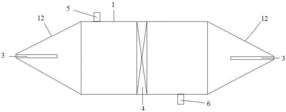
[0049] Such as image 3 As shown, a kind of ultraviolet light photocatalytic oxidation device comprises reactor 1, and the two ends of described reactor 1 are all connected with reflector 12, and the inner surface of described reflector 12 is provided with ultraviolet reflective coating, and described The reflector 2 is connected with a first ultraviolet lamp 3, the inner wall of the reactor 1 is connected with a photocatalytic oxide layer 4, and either side of the reactor 1 connected with the reflector 12 is provided with an air inlet 5 A gas outlet 6 is opened on the other side of the reactor, and the photocatalytic oxidation layer 4 is located between the gas inlet 5 and the gas outlet 6 .
[0050] The number of layers of the photocatalytic oxidation layer 4 is one.
[0051] The shape of the reflector 12 is set as a hollow cone.
[0052] The apex angle of the air cone is 30° to 120°, preferably 60°.
[0053] The material of the ultraviolet reflective coating is preferabl...
PUM
| Property | Measurement | Unit |
|---|---|---|
| Cone angle | aaaaa | aaaaa |
Abstract
Description
Claims
Application Information
 - R&D
- Intellectual Property
- Life Sciences
- Materials
- Tech Scout
- Unparalleled Data Quality
- Higher Quality Content
- 60% Fewer Hallucinations
Browse by: Latest US Patents, China's latest patents, Technical Efficacy Thesaurus, Application Domain, Technology Topic, Popular Technical Reports.
© 2025 PatSnap. All rights reserved.Legal|Privacy policy|Modern Slavery Act Transparency Statement|Sitemap|About US| Contact US: help@patsnap.com