Uniform-stirring adhesive stirring device

A stirring device and uniform stirring technology, which is applied in the direction of mixer accessories, mixers with rotating containers, mixers, etc., can solve problems affecting the quality of adhesive glue, uneven mixing of raw materials, etc., and achieve stable stirring, uniform stirring, and mixing uniform effect

Inactive Publication Date: 2017-05-31
WUXI HITXINCHENG POLYMER TECH
0 Cites 12 Cited by

AI-Extracted Technical Summary

Problems solved by technology

[0003] The purpose of the present invention is to provide a uniformly stirred adhesive stirring device, which has the advantage of uniformly stirring, and solves the problem of the existing adhesive stirring device mentioned in the backg...

Abstract

The invention discloses a uniform-stirring adhesive stirring device. The uniform-stirring adhesive stirring device comprises a housing and a housing cover, wherein the bottom of the internal cavity of the housing is fixedly connected with the bottom of a motor box, a motor is fixedly mounted in the motor box, one end of an output shaft of the motor penetrates through a top plate of the motor box and is fixedly connected with the bottom end of a connecting rod, the top end of the connecting rod is fixedly connected with the bottom of a stirring barrel, and snapping blocks are fixedly mounted at the top of the housing. According to the uniform-stirring adhesive stirring device, through arranging the motor, the connecting rod and the stirring barrel which are matched with one another, materials for preparing an adhesive are mixed and stirred and are melted so as to form the adhesive; through arranging the snapping blocks and forming snapping grooves in the housing cover, the housing cover is in snap connection with the housing; through a fixing shaft, stirring shafts, stirring plates and stirring screens which are matched with one another, the area of contact of various kinds of liquid can be larger during the stirring of the stirring device, so that the adhesive is mixed more uniformly, and thus, a uniform stirring effect is achieved.

Application Domain

Technology Topic

Image

  • Uniform-stirring adhesive stirring device
  • Uniform-stirring adhesive stirring device
  • Uniform-stirring adhesive stirring device

Examples

  • Experimental program(1)

Example Embodiment

[0016] The technical solutions in the embodiments of the present invention will be clearly and completely described below in conjunction with the accompanying drawings in the embodiments of the present invention. Obviously, the described embodiments are only a part of the embodiments of the present invention, rather than all the embodiments. Based on the embodiments of the present invention, all other embodiments obtained by those of ordinary skill in the art without creative work shall fall within the protection scope of the present invention.
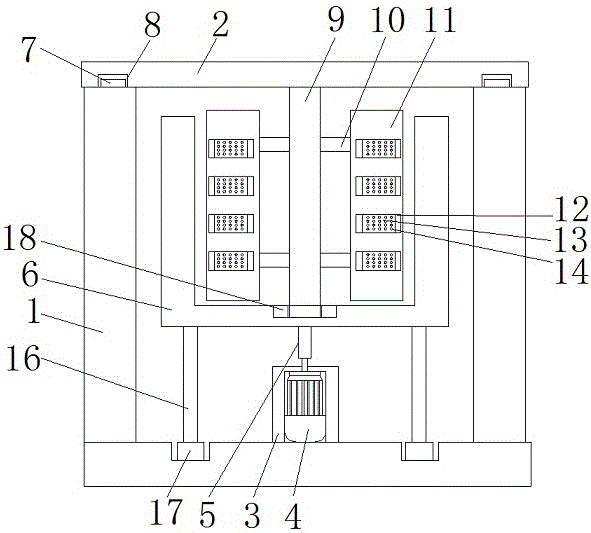
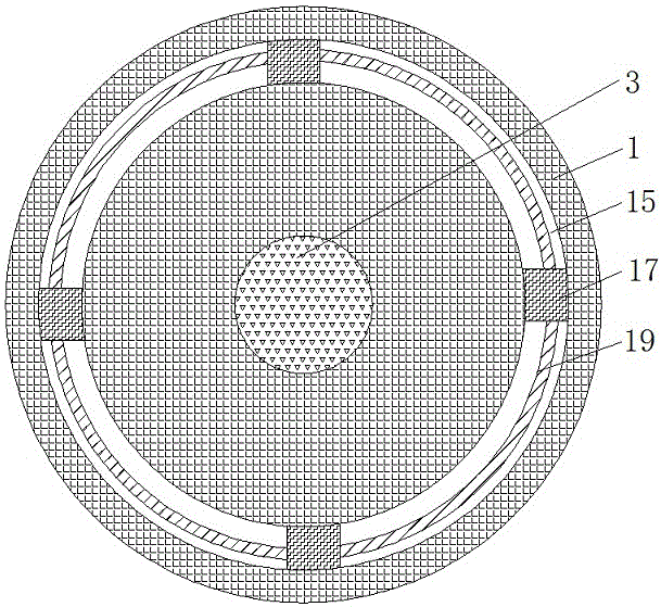
[0017] See Figure 1-3 , A uniformly stirred adhesive stirring device, comprising a shell 1 and a shell cover 2. The bottom of the inner cavity of the shell 1 is fixedly connected with the bottom of the motor box 3. The motor 4 is fixedly installed in the motor box 3, and the motor box 3 is used for fixing Motor 4, when the motor 4 rotates, the body of the motor 4 does not rotate, the output shaft of the motor 4 rotates, one end of the output shaft of the motor 4 penetrates the top plate of the motor box 3 and is fixedly connected to the bottom end of the connecting rod 5. The power supply of 4 is external. When the output shaft of the motor 4 rotates, it will drive the connecting rod 5 to rotate. The top of the connecting rod 5 is fixedly connected with the bottom of the mixing barrel 6. The mixing barrel 6 is used to hold the adhesive material and make it The connecting rod 5 is connected to the axis of the bottom of the mixing barrel 6. When the connecting rod 5 rotates, it will drive the mixing barrel 6 to rotate around the connecting rod 5. When the mixing barrel 6 rotates, it will drive the internal adhesive making materials Rotate to mix to form a binder. The bottom of the inner cavity of the mixing barrel 6 is embedded with a bearing 18, and the opening radius at the axis of the bearing 18 is three centimeters. The bottom of the inner cavity of the housing 1 is provided with an annular chute 15 and the mixing barrel 6 The bottom of the support rod 16 is fixedly connected to the top of the support rod 16, and the other end of the support rod 16 is inserted into the annular slide groove 15 at the bottom of the inner cavity of the housing 1 and is fixedly connected with the slider 17 in the annular slide groove 15, and the slider 17 is slidably connected to In the annular chute 15, the number of support rods 16 is four, and the sliders 17 are fixedly connected by arc-shaped connecting rods 19, and the mixing barrel 6 is fixed by the four support rods 16 to make it more stable and prevent rotation When the mixing barrel 6 shakes, the internal adhesive spills and damages the device. When the mixing barrel 6 rotates, it will drive the bottom support rod 16 to rotate around the center of the bottom of the mixing barrel 6, and drive the four sliders 17 in the ring The chute 15 makes a circular motion, and the four sliders 17 are fixedly connected by the arc-shaped connecting rod 19, so that the mixing barrel 6 is more stable. The top of the housing 1 is fixedly installed with a clamping block 7, and the bottom of the housing cover 2 is far away from the center of the circle. A card slot 8 is provided, and the card block 7 is clamped in the card slot 8. The housing cover 2 is clamped on the housing 1 through the cooperation of the card slot 8 and the card block 7. The center of the bottom circle of the housing cover 2 is connected to the fixed shaft 9 The top end is fixedly connected. The radius of the fixed shaft 9 is three centimeters. The radius of the fixed shaft 9 is the same as the opening radius of the bearing 18. When the housing cover 2 is clamped on the housing 1, the bottom end of the fixed shaft 9 is inserted into the opening of the bearing 18, Make the fixed shaft 9 more stable and will not shake during stirring. The fixed shaft 9 is provided with two stirring shafts 10 from top to bottom, and the other ends of the two stirring shafts 10 are respectively fixedly connected to one side of the stirring plate 11 , The stirring plate 11 is provided with a through hole 12, a stirring net 13 is fixedly installed in the through hole 12, the number of the stirring net 13 is twenty-four pieces, and the three pieces of stirring net 13 are fixedly installed in the through hole 12 as a group, The stirring mesh 13 is provided with stirring holes 14. The stirring plate 11 and the stirring shaft 10 are symmetrically arranged on both sides of the fixed shaft 9 with the fixed shaft 9 as a symmetrical axis. When the mixing barrel 6 rotates, it will drive the internal adhesive to make materials When rotating, the adhesive will pass through the stirring holes 14 on the stirring mesh 13 on the stirring plate 11, and the stirring holes 14 will divide the adhesive so that the mixing of the adhesive will be more uniform, and three pieces of stirring net 13 will be arranged to make the mixing effect better.
[0018] When in use, put the material for making the adhesive into the mixing barrel 6, fix the housing cover 2 on the housing 1 through the card slot 8 and the card block 7, start the motor 4, and the output shaft of the motor 4 rotates through the connection The rod 5 drives the mixing barrel 6 to rotate. When the mixing barrel 6 rotates, the internal adhesive material is mixed and stirred to make it mixed into an adhesive. When the adhesive material is rotated and mixed in the mixing barrel 6, it passes through the mixing plate The stirring net 13 provided on the through hole 12 of 11 is divided by the stirring hole 14 on the stirring net 13 to divide the flow so as to make the stirring more uniform.
[0019] Although the embodiments of the present invention have been shown and described, those of ordinary skill in the art can understand that various changes, modifications, and substitutions can be made to these embodiments without departing from the principle and spirit of the present invention. And variations, the scope of the present invention is defined by the appended claims and their equivalents.

PUM

no PUM

Description & Claims & Application Information

We can also present the details of the Description, Claims and Application information to help users get a comprehensive understanding of the technical details of the patent, such as background art, summary of invention, brief description of drawings, description of embodiments, and other original content. On the other hand, users can also determine the specific scope of protection of the technology through the list of claims; as well as understand the changes in the life cycle of the technology with the presentation of the patent timeline. Login to view more.

Similar technology patents

Drum type easily cleaned concrete stirring device

InactiveCN108568899AIncrease vibration amplitudeWell mixedTransportation and packagingMixer accessoriesMotor shaftSpiral blade
Owner:HUIAN WEIKE ELECTRONICS TECH CO LTD

Classification and recommendation of technical efficacy words

  • Well mixed
  • Stir well

Simulation test device for debris flow and test method

PendingCN106841573AStir wellAdjustable inclinationEarth material testingHydraulic ramLift system
Owner:NORTHWEST RES INST CO LTD OF C R E C

Chemical raw material stirring and drying device

Owner:长沙德科投资管理咨询有限公司
Why Eureka
Try Eureka