
Paper shredder and working method thereof

A paper shredder and paper shredding technology, which is applied in papermaking, textile and papermaking, fiber raw material processing, etc., can solve the problems of ink processing, inability to guarantee information leakage prevention, and inability to solve leakage prevention, so as to save time and prevent information leakage , the effect of increasing the difficulty of recovery

Inactive Publication Date: 2017-05-31
STATE GRID CORP OF CHINA +1
View PDF5 Cites 16 Cited by
  • Summary
  • Abstract
  • Description
  • Claims
  • Application Information

AI Technical Summary

Problems solved by technology

This invention cannot solve the problem of preventing leakage of information on the paper before it is shredded. After the paper is shredded by the shredding roller, the shredded paper is laid on the filter screen according to the time of shredding. Liquid soaking cannot process all types of ink. As far as the existing technology is concerned, some processed paper can restore information, which cannot guarantee absolute leakage prevention of information

Method used


Image

  • Paper shredder and working method thereof
  • Paper shredder and working method thereof
  • Paper shredder and working method thereof

Examples


Embodiment Construction

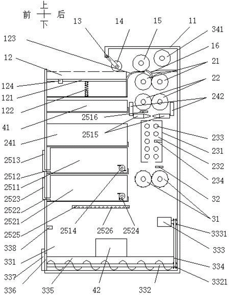
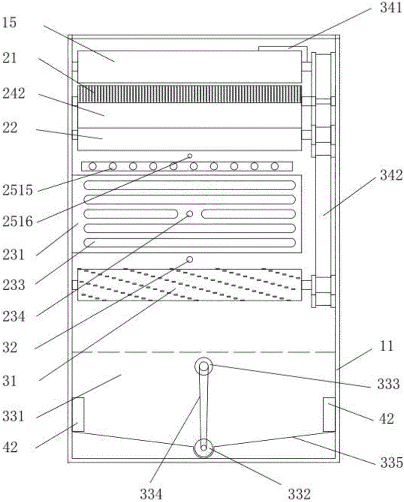
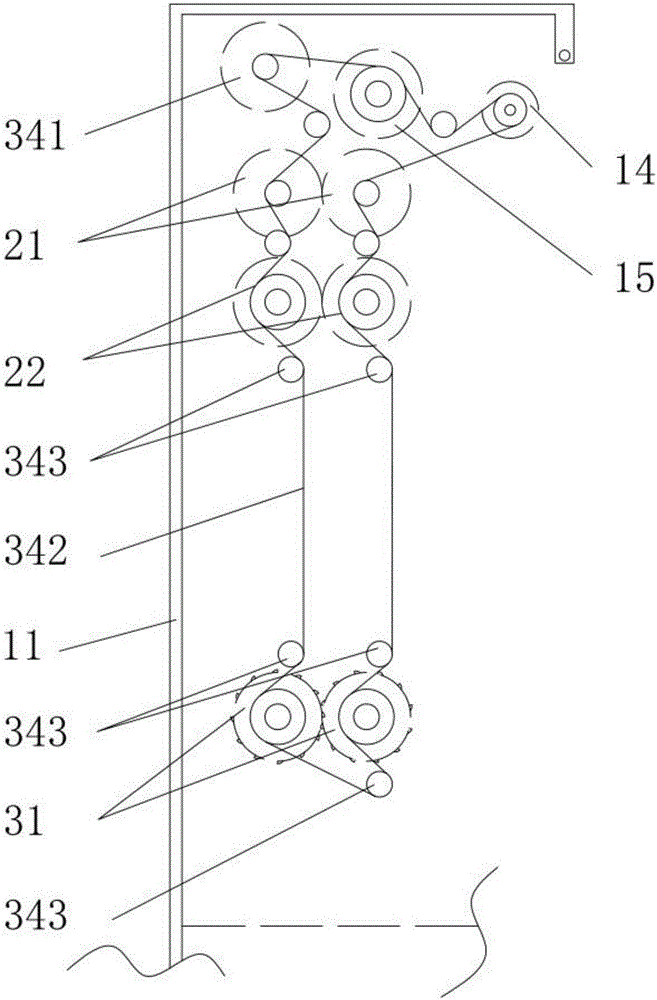
[0055] The present invention is described in further detail now in conjunction with accompanying drawing. These drawings are all simplified schematic diagrams, which only illustrate the basic structure of the present invention in a schematic manner, so they only show the configurations related to the present invention.

[0056] In addition, it should be noted that, unless otherwise specified or pointed out, the terms "front", "rear", "left", "right", "upper", "lower" and other descriptions that may be involved in the specification are only used to distinguish The various components, elements, steps, etc. in the specification are not used to represent the logical relationship or sequence relationship between the various components, elements, and steps.

[0057] The related words of "working" of "shredding motor" and "discharging motor" are only used for convenience of description, and do not represent the specific running direction of the motor.

[0058] The present invention ...


PUM


Abstract

The invention relates to a paper shredder and a working method thereof. The paper shredder comprises a shell, a paper feeding assembly, a paper treating assembly, a discharging assembly, a power assembly and a controller. The paper feeding assembly comprises a storage box, a paper feeding table, a paper conveying roller and a paper feeding roller, and a guide plate is arranged behind the paper feeding roller; the paper treating assembly comprises a traction roller and a steel burr roller, dust collecting pipes are arranged on the two sides of the burr roller, and a painting spraying nozzle, a drying assembly, a paper shredding sensor and a paper shredding cutter roller are sequentially arranged below the steel burr roller; a dust collector, an upper material liquid box assembly and a lower material liquid box assembly are arranged below the controller; the discharging assembly comprises a paper shredding cavity with an ultrasonic generator, a discharging screw and a discharging motor, and a discharging sensor is arranged in the paper shredding cavity; the power assembly comprises a paper shredding motor, and all roller shafts are connected with the paper shredding motor through paper shredding synchronous belt; and the controller is connected with all elements through wires. The invention further discloses a working method of the paper shredder. By means of the paper shredder and the working method, before paper shredding, earlier stage leakage-proof treatment can be carried out, shredded paper reaches the micron order after shredding is carried out, and information leakage is prevented.

Description

technical field [0001] The invention belongs to the field of office supplies, and in particular relates to a shredder and a working method thereof. Background technique [0002] With the advent of modern office, the value of information is more and more important, therefore, some information needs to be kept confidential. In information transmission, paper is the most commonly used as the transmission medium of information. Therefore, the destruction of paper after use is particularly important. Now commonly used shredders, the shredding method refers to that when the paper is processed by the shredder, it is cut by a shredder knife. Broken into strips. However, the current paper shredders still have some disadvantages in the process of using them. First, most of the paper shredders are broken into strips, and after being crushed, they fall on the top layer of the shredder. It can be recovered, which is not conducive to the confidentiality of information. Secondly, it may ...

Claims


Application Information

Patent Timeline
Patent Type & Authority Applications(China)
IPC IPC(8): B02C18/14B02C18/16B02C18/22B02C23/36B02C23/04
CPCB02C18/0007B02C18/14B02C18/16B02C18/2216B02C18/2283B02C23/36B02C2018/168B02C2201/06D21B1/345
Inventor 张兆才王辉刘远新赵培芹邹玉魁杨帆于国龙王思聪
Owner STATE GRID CORP OF CHINA
Learn More