Pneumatic clamping general lathe

A common lathe, clamping technology, applied in the field of common lathes, can solve the problems of deformation of the workpiece, failure to master the strength of pulling the chuck S1, time-consuming and labor-intensive problems, and achieve the effect of reducing rigid impact damage

Active Publication Date: 2017-05-31
重庆完镁镁制品有限公司
View PDF9 Cites 3 Cited by
  • Summary
  • Abstract
  • Description
  • Claims
  • Application Information

AI Technical Summary

Problems solved by technology

This method of installing and adjusting the tightness of the chuck has been used for decades. However, in the process of use, on the one hand, due to manual pulling, it is time-consuming, laborious and inefficient; on the other hand, it is also the biggest defect here. That is, the strength of pulling the chuck S1 cannot be grasped manually, which will cause the workpiece e to be over-clamped and deformed, or the axis of the clamping will be shifted, resulting in a huge error in machining accuracy

Method used


Image

  • Pneumatic clamping general lathe
  • Pneumatic clamping general lathe
  • Pneumatic clamping general lathe

Examples


Embodiment Construction

[0039] The implementation of the present invention will be illustrated by specific specific examples below, and those skilled in the art can easily understand other advantages and effects of the present invention from the contents disclosed in this specification.

[0040] Below in conjunction with accompanying drawing and embodiment the present invention will be further described:

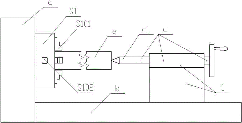
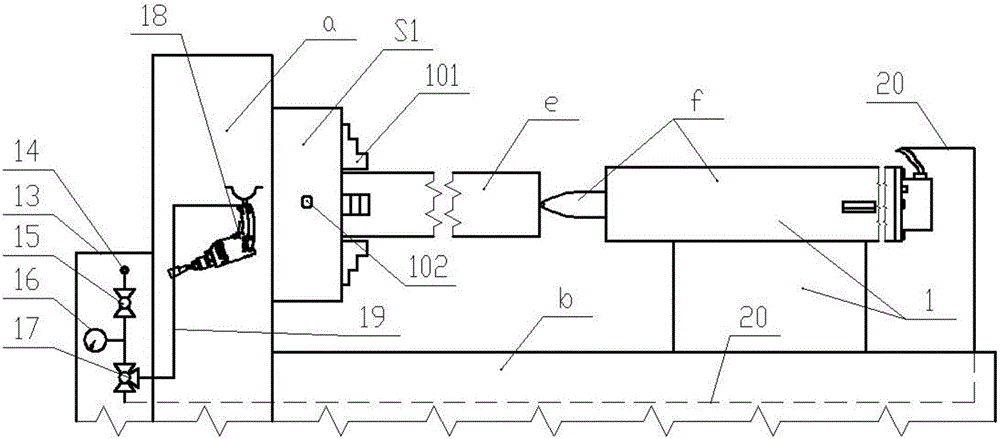
[0041] Such as image 3 As shown, a pneumatic clamping type ordinary lathe includes a headstock a and a chuck S1 connected to the main shaft in the headstock a, and a tailstock 1 with a top on the machine tool guide rail b; on the chuck S1 There is a wrench hole S10. What is different from existing common lathes is; also comprise pneumatic system 13, described pneumatic system 13 comprises cylinder, and the compressed gas output port 14 of cylinder is connected with three-way valve 17 through control valve 15, in described control valve 15 and three-way A precision gas pressure gauge 16 is provid...


PUM

PropertyMeasurementUnit
angleaaaaaaaaaa

Abstract

The invention discloses a pneumatic clamping general lathe. The pneumatic clamping general lathe comprises a pneumatic spanner and a pneumatic ejecting device; the pneumatic spanner includes a pneumatic gun drill; a drill bit of the pneumatic gun drill is replaced to a cylindrical first connecting rod; the first connecting rod is connected with a second connecting rod for extending into a spanner head; an arc piece body is arranged at the extension end of the second connecting rod; an arc groove for mounting a spring is formed in the bottom of an extension hole; and when the second connecting rod extends into the spanner head and rotates to a proper position, a spring is compressed, and the arc end of the arc piece body is connected with the end surface of one end, provided with the spring, of the arc groove. The pneumatic ejecting device includes a tail base and a tip; a sleeve is embedded in the tail base; a sealing ring is arranged on the right end surface of the inner wall of the sleeve; the tip is arranged at the tail end of an output shaft of a cylinder; a spiral groove is formed in the inner wall of the sleeve, and gradually extends and expands from the right end of the sleeve to the left end; and multiple laps of grooves are formed in the surface of the output shaft. The lathe can quickly realize clamping of workpieces, and effectively controls the clamping strength of the workpieces.

Description

technical field [0001] The invention belongs to the technical field of machining, and in particular relates to a common lathe. Background technique [0002] Lathes play a pivotal role in metal cutting. Commonly used lathes are classified according to their degree of automation. There are two main types, one is CNC lathes controlled by servo system, and the other is ordinary lathes, whether it is CNC lathes or ordinary lathes , are set as figure 1 The shown spindle box a, chuck S1, machine tool guide rail b, and tailstock 1 with top system c, usually the head of the lathe is equipped with the above-mentioned chuck S1, the end of the bed is equipped with a tailstock 1, and the tailstock 1 is equipped with There is a top system c. The top c1 in the top system c is set parallel to the guide rail b of the machine tool. The top and the tailstock 1 are threadedly connected or the screw is directly used and its end is processed into a conical point as the top c1. There is a handwh...

Claims


Application Information

Patent Timeline
Patent Type & Authority Applications(China)
IPC IPC(8): B23B3/06B23B45/04B25B21/00
CPCB23B3/06B23B45/04B25B21/00
Inventor 李朝安
Owner 重庆完镁镁制品有限公司
Why Eureka
Try Eureka