Cutting blade and cutting tool
A technology for cutting blades and cutting tools, applied in cutting blades, tools for lathes, turning equipment, etc., can solve the problems of increased deformation of fasteners, vibration and detachment of cutting blades, etc., and achieve vibration attenuation and long cutting life , the effect of suppressing collapse
- Summary
- Abstract
- Description
- Claims
- Application Information
AI Technical Summary
Problems solved by technology
Method used
Image

Examples
Embodiment 1
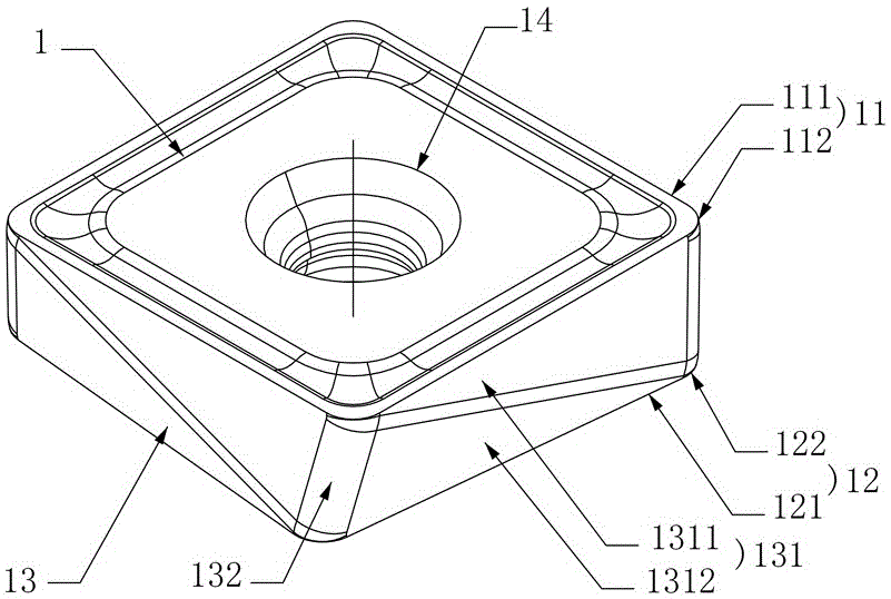
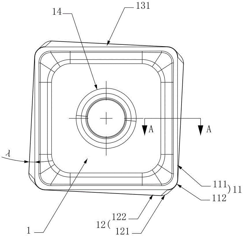
[0040] Figure 1 to Figure 3 The first embodiment of the cutting insert of the present invention is shown, the cutting insert comprises a insert body 1, the insert body 1 comprises an upper cutting portion 11 and a lower cutting portion 12, the upper cutting portion 11 is composed of a plurality of upper main cutting edges 111 and upper Turning cutting edges 112 are connected in sequence, and the lower cutting portion 12 is composed of a plurality of lower main cutting edges 121 and lower turning cutting edges 122 connected in sequence. The upper main cutting edge 111 and the lower main cutting edge 121 have the same negative acute angle cutting relief angle, At least a part of the upper main cutting edge 111 on the same side protrudes from the lower main cutting edge 121 on the same side, and at least a part of the lower main cutting edge 121 on the same side protrudes from the upper main cutting edge 111 on the same side. In this structure, the upper cutting part 11 is compo...
Embodiment 2
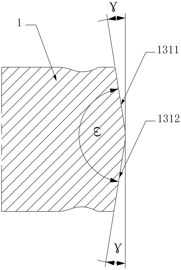
[0046] Figure 1 to Figure 3 Shows the second embodiment of the cutting insert of the present invention, the cutting insert is basically the same as Embodiment 1, the only difference is: in this embodiment, the upper side 1311 and the lower side 1312 are at the diagonal positions of the main side 131 The upper turning cutting edge 112 on the right intersects the lower turning cutting edge 122 on the left. In this structure, because in the same main side surface 131, the upper main cutting edge 111 or the lower main cutting edge 121 participating in the side cutting in the upper cutting unit or the lower cutting unit participating in the cutting and the corresponding lower main cutting edge 121 or upper The main cutting edge 111 interacts with each other, the upper main cutting edge 111 or the lower main cutting edge 121 of the face cutting cannot participate in the cutting with a complete positive relief angle, and the upper cutting unit or the lower cutting unit participating...
Embodiment 3
[0048] Figure 1 to Figure 3 Shows the third embodiment of the cutting insert of the present invention, the cutting insert is basically the same as Embodiment 1, the only difference is that eight upper cutting units with the same cutting shape are arranged on the upper surface, and eight upper cutting units with the same cutting shape are arranged on the lower surface. Eight lower cutting units with the same cutting shape, so that the cutting blade can be used 16 times, which has a better cost performance advantage. The rest of the parts that are not discussed are completely the same as the first embodiment of the disclosed cutting insert of the present invention, and will not be repeated here.
PUM
 Abstract
Description
Claims
Application Information
 - R&D
- Intellectual Property
- Life Sciences
- Materials
- Tech Scout
- Unparalleled Data Quality
- Higher Quality Content
- 60% Fewer Hallucinations
Browse by: Latest US Patents, China's latest patents, Technical Efficacy Thesaurus, Application Domain, Technology Topic, Popular Technical Reports.
© 2025 PatSnap. All rights reserved.Legal|Privacy policy|Modern Slavery Act Transparency Statement|Sitemap|About US| Contact US: help@patsnap.com