Laser cutting machine

A cutting machine and cutting head technology, applied in laser welding equipment, welding equipment, metal processing equipment, etc., can solve problems such as defocusing, achieve the effects of ensuring cutting accuracy, improving applicability, and solving defocusing problems

Inactive Publication Date: 2017-05-31
GUANGDONG ZHENGYE TECH
View PDF7 Cites 11 Cited by
  • Summary
  • Abstract
  • Description
  • Claims
  • Application Information

AI Technical Summary

Problems solved by technology

[0005] In view of this, the object of the present invention is to provide a three-dimensional laser cutting machine, which solves the defocus problem in the cutting process

Method used


Image

  • Laser cutting machine
  • Laser cutting machine
  • Laser cutting machine

Examples


Embodiment Construction

[0033] The following will clearly and completely describe the technical solutions in the embodiments of the present invention with reference to the accompanying drawings in the embodiments of the present invention. Obviously, the described embodiments are only some, not all, embodiments of the present invention. Based on the embodiments of the present invention, all other embodiments obtained by persons of ordinary skill in the art without making creative efforts belong to the protection scope of the present invention.

[0034] The core of the present invention is to provide a three-dimensional laser cutting machine, which solves the defocus problem in the cutting process.

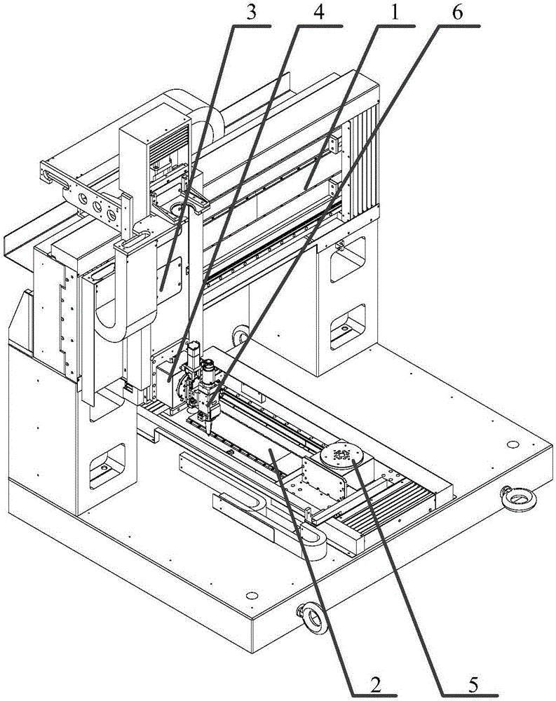
[0035] Please refer to figure 1 , figure 1 It is a structural diagram of a three-dimensional laser cutting machine provided by the present invention.

[0036] A specific embodiment of the machine tool provided by the present invention includes a machine tool and a control terminal for controlling the mac...


PUM


Abstract

The invention discloses a three-dimensional laser cutting machine. The three-dimensional laser cutting machine comprises a machine tool, wherein the machine tool comprises an X-axis assembly used for driving a cutting head in an X direction, a Z-axis assembly used for driving the cutting head in a Z direction, a Y-axis assembly used for driving a workpiece in a Y direction, a workpiece rotary shaft assembly used for driving the workpiece to rotate, a cutting head rotary shaft assembly and a follower shaft assembly; the workpiece rotary shaft assembly is capable of driving the workpiece to rotate in the Z direction; the cutting head rotary shaft assembly is capable of driving the cutting head to rotate in the Y direction; the follower shaft assembly is arranged on the cutting head rotary shaft assembly; the cutting head is arranged in the follower shaft assembly; a capacitive sensor is arranged at the nozzle of the cutting head; and each two of the X direction, the Y direction and the Z direction are mutually vertical. The three-dimensional laser cutting machine further comprises a control terminal used for carrying out control operation on the machine tool. The follower shaft assembly is capable of automatically adjusting the height of the cutting head according to the change of the surface of a cutting sample to ensure a constant distance between the cutting head and the cutting sample during a three-dimensional laser cutting process, thereby solving the out-of-focus problem generated during a cutting process.

Description

technical field [0001] The invention relates to the technical field of laser cutting equipment, in particular to a laser cutting machine. Background technique [0002] With the development of laser cutting technology, laser cutting is more and more widely used in industrial processing due to its unique advantages. Among them, the three-dimensional laser cutting machine is widely used in many fields such as the automobile industry, the aerospace industry, and precision hardware because of its flexible cutting path and strong applicability. [0003] During the laser cutting process, the cutting sample should be kept at the laser focal point as much as possible to achieve the best cutting effect. However, the surface of the sample actually cut by the current laser cutting machine is different from the surface of the sample model, especially in the three-dimensional sample, which leads to defocus during the cutting process and makes the cutting effect worse, [0004] Therefore...

Claims


Application Information

Patent Timeline
Patent Type & Authority Applications(China)
IPC IPC(8): B23K26/38B23K26/08B23K26/70
CPCB23K26/38B23K26/08B23K26/702
Inventor 刘林徐地明龚成万张善基林克肖磊徐地华梅领亮
Owner GUANGDONG ZHENGYE TECH
Why Eureka
Try Eureka