Machine tool

A machine tool and chip technology, applied in the field of machine tools with movable nozzles, can solve the problems of control, inability to flush chips, and inability to change nozzle orientation, etc., to achieve efficient flushing and reduce power consumption

Active Publication Date: 2017-05-31
FANUC LTD
View PDF12 Cites 13 Cited by
  • Summary
  • Abstract
  • Description
  • Claims
  • Application Information

AI Technical Summary

Problems solved by technology

[0006] However, in the above-mentioned prior art, all of them spray liquid onto the workpiece or workbench being processed, so that the chips adhering to and accumulating on the workpiece or the upper surface of the workbench fall down to the lower part of the cover, and it is impossible to prevent the chips adhering to and accumulating on the cover. Flush chips from the inner surface of the
In the prior art described in the above-mentioned Japanese Patent Application Laid-Open No. 03-026451, since the driving is performed for each pipe equipped with a nozzle, even if there are a plurality of nozzles, they perform the same operation, and it is not possible to direct the nozzles to individual directions. It is controlled and can only perform pre-programmed actions, so that the direction of the nozzle cannot be changed according to the situation
[0007] None of the prior art mentioned above can individually control the discharge of the liquid from the nozzle

Method used


Image

  • Machine tool
  • Machine tool
  • Machine tool

Examples


Embodiment Construction

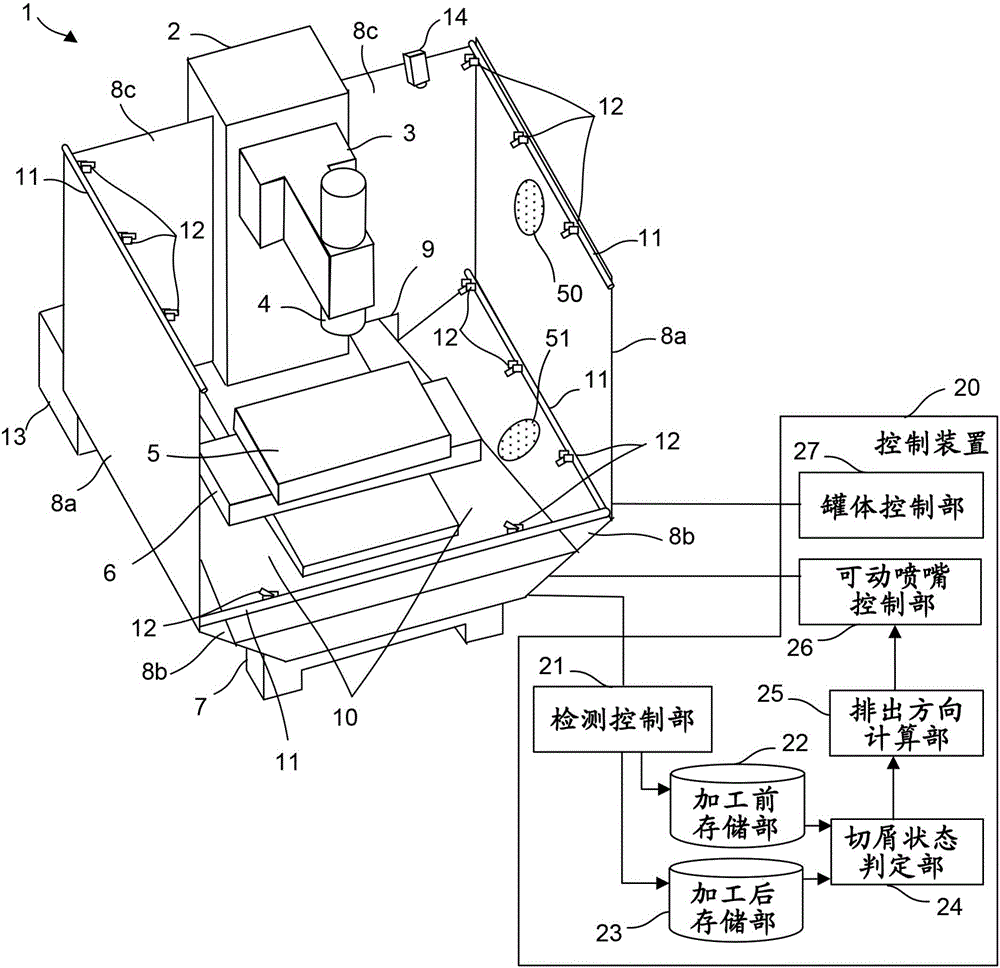
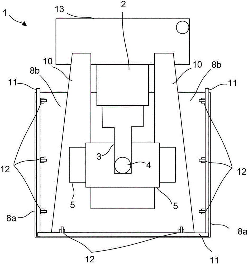
[0023] use Figure 1A as well as Figure 1B A brief configuration of a machine tool according to an embodiment of the present invention will be described.

[0024] The machine tool 1 includes a table 5 movably provided via a saddle 6 , and a spindle 4 attached to a spindle head 3 supported by a column 2 . The table 5 and the spindle 4 are provided on a bed 7 . The table 5 is provided movably by a saddle 6 , and a workpiece to be processed is fixed on the table 5 . A tool for machining the workpiece can be attached to the spindle 4 .
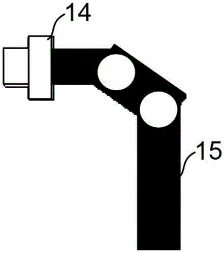
[0025] The entire machining area of ​​the machine tool 1 where workpieces are machined is covered with covers 8 (side covers 8 a , bottom covers 8 b , and rear covers 8 c ) that prevent chips and cutting fluid generated during machining from scattering around. In addition, in the machine tool 1, pipes 11 are arranged from the outside of the cover 8 to the inside of the cover 8, and a plurality of nozzles whose discharge directions can be change...


PUM


Abstract

A machine tool has a cover that prevents chips generated by machining and cutting fluid from scattering around and a plurality of movable nozzles with liquid discharge directions thereof being movable so as to wash out chips that have adhered to or accumulated on an inner surface of the cover. The machine tool is capable of changing a discharge direction of each of the movable nozzles individually. The machine tool compares the state of the inside of the cover before start of machining with the state of the inside of the cover after chips are generated to determine an adhesion or accumulation state of chips. The machine tool thus calculates the liquid discharge direction to wash out chips from the movable nozzles based on a result of the determination.

Description

technical field [0001] The present invention relates to a machine tool having a movable nozzle for cleaning inside the machine. Background technique [0002] A cover is provided on the machine tool so that chips generated during machining and cutting fluid used in machining do not scatter around the machine tool. By providing a cover, chips and cutting fluid can be prevented from scattering around the machine tool, but chips may adhere to and accumulate on the inner surface of the cover as machining continues. [0003] As a technique for preventing the accumulation of chips in such a cover, for example, Japanese Patent Application Laid-Open No. 05-067446 discloses a technique in which a scraper is provided on a saddle that moves back and forth during a machining cycle, and a chip flushing liquid supply pipe is provided on an oil pan. , and a nozzle is provided in the chip flushing liquid supply pipe, whereby the scraper collects the chips when the saddle moves forward and b...

Claims


Application Information

Patent Timeline
Patent Type & Authority Applications(China)
IPC IPC(8): B23Q11/00B23Q11/08
CPCB23Q11/005B23Q11/08B08B9/00B08B17/00B08B17/025B23Q11/0891B23Q11/1076B05B12/04B05B13/0405B05B13/0431B08B3/024B23Q17/2452Y02P70/10B23Q11/0042B23Q17/2433
Inventor 奥田真司
Owner FANUC LTD
Why Eureka
Try Eureka