An assembly method of an integral hydraulic stamping machine

An assembly method and punching machine technology, applied in punching machines, presses, manufacturing tools, etc., can solve the problems of steel consumption, heavy punching machine structure, high production cost, and achieve lower production costs, uniform rolling friction, and lower consumption. Effect

Active Publication Date: 2018-07-10
安徽中瑞机床制造有限公司
View PDF6 Cites 0 Cited by
  • Summary
  • Abstract
  • Description
  • Claims
  • Application Information

AI Technical Summary

Problems solved by technology

[0005] However, the hydraulic stamping machine disclosed in the above-mentioned patent is only suitable for working conditions with a relatively small stamping force. For the working conditions requiring a large stamping force (for example, stamping parts with a thicker thickness), the stamping machine in the prior art has a heavy structure and consumes a lot of energy. Large amount of steel, high production cost

Method used


Image

  • An assembly method of an integral hydraulic stamping machine
  • An assembly method of an integral hydraulic stamping machine
  • An assembly method of an integral hydraulic stamping machine

Examples


Embodiment 1

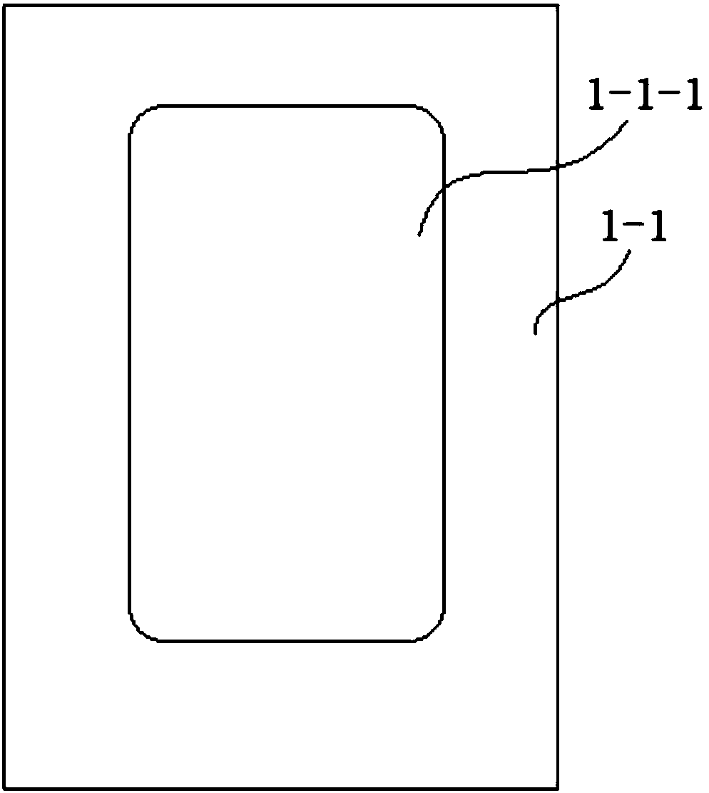
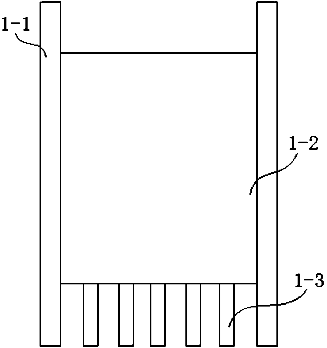
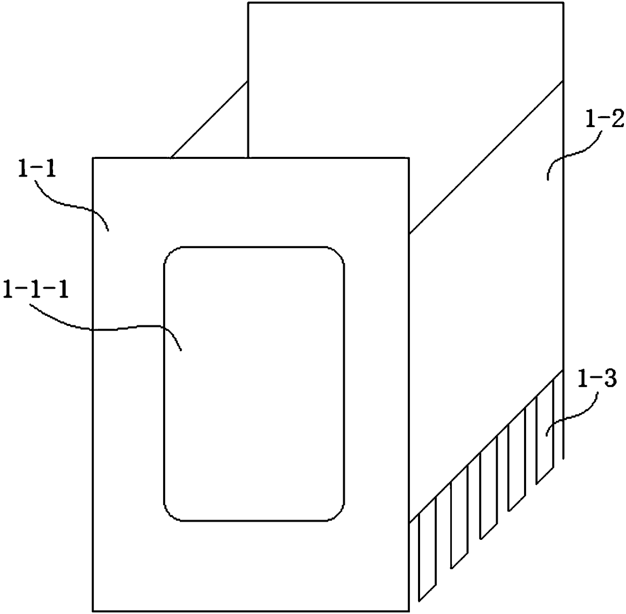
[0056] refer to Figure 1-9 , an integral hydraulic punching machine in this embodiment, comprising a main frame, the main frame includes two vertical plates 1-1 placed longitudinally on the front and rear sides of the two vertical plates 1-1, and the left and right sides of the two vertical plates 1-1 pass through the corresponding The side connection plate 1-2 is connected; the bottom end of the side connection plate 1-2 is connected with several parallel bottom reinforcement plates 1-3; the vertical plate 1-1 is provided with a vertical plate through hole 1-1-1, the The through hole 1-1-1 of the vertical plate is a rectangular through hole, and the four corners of the rectangular through hole are rounded;

[0057] In this embodiment, the main frame with the above-mentioned structure can significantly reduce the consumption of steel on the premise of ensuring the good strength, rigidity and vibration resistance of the fuselage itself, especially for working conditions that r...

Embodiment 2

[0077] refer to Figure 10 , an assembly method of the integral hydraulic stamping machine as described in embodiment 1, comprising the following steps:

[0078] Step 1, set up hoisting holes on the four corners of the vertical plate 1-1 respectively, so as to facilitate the hoisting of the vertical plate 1-1;

[0079] Step 2. First, place the two vertical boards 1-1 horizontally, and then adjust the distance between the two vertical boards 1-1 to the specified value. Because the vertical boards 1-1 are high and difficult to locate , in this embodiment, the two vertical plates 1-1 are laid down horizontally, which reduces the difficulty of processing;

[0080] Step 3: Correspondingly connect the four corners of the two vertical plates 1-1 through the four positioning connecting columns. In this embodiment, first determine the distance between the two vertical plates 1-1 through the four positioning connecting columns, and then Subsequent processing is carried out to avoid th...


PUM


Abstract

The invention discloses an assembling method of an all-in-one hydraulic punch and belongs to the field of punching equipment. The assembling method of the all-in-one hydraulic punch comprises the following steps: step 1, separately forming lifting holes in the four corners of vertical plates; step 2, first, transversely laying both of the two vertical plates down, and then adjusting a distance between the two vertical plates to a standard value; step 3, correspondingly connecting the four corners of the two vertical plates through four locating connecting columns; step 4, correspondingly welding side connecting plates at the left and right sides of the two vertical plates; step 5, welding a plurality of bottom reinforcing plates parallel with each other at the bottom ends of the side connecting plates; and step 6, cutting the four locating connecting columns from the vertical plates. The main purpose of the invention is to provide the assembling method of the all-in-one hydraulic punch. The steel consumption of the assembled punch is reduced, and the production cost is greatly reduced.

Description

technical field [0001] The invention relates to the field of punching equipment, and more specifically, relates to an assembly method of an integral hydraulic punching machine. Background technique [0002] Stamping is a commonly used processing technology in metal sheet processing. It relies on punching machines and molds to exert external force on the sheet-like strips to cause plastic deformation or separation of the strips, thereby obtaining stamped parts of the required shape and size. Stamping includes two kinds of deformation process and separation process. The separation process is also called blanking. Its purpose is to separate the stamped parts from the strip along a certain contour line, while ensuring the quality requirements of the separation section. The purpose of the forming process is to make the strip plastically deform without breaking the billet to make a blank of the required shape and size. The blank is then subjected to subsequent grinding, polishing ...

Claims


Application Information

Patent Timeline
Patent Type & Authority Patents(China)
IPC IPC(8): B30B15/04B30B1/32B30B15/02B30B15/06
CPCB30B1/32B30B15/02B30B15/04B30B15/064
Inventor 夏尧林夏业春戴庆
Owner 安徽中瑞机床制造有限公司
Why Eureka
Try Eureka