
A kind of forming method of composite metal integrated tie rod

A molding method and tie rod technology, applied in the field of drones, can solve problems such as difficult control of bonding quality, low connection efficiency, and heavy weight, and achieve the effects of light weight, enhanced integrated strength, and reduced weight

Active Publication Date: 2019-09-06
CHINA ACAD OF AEROSPACE AERODYNAMICS
View PDF4 Cites 0 Cited by
  • Summary
  • Abstract
  • Description
  • Claims
  • Application Information

AI Technical Summary

Problems solved by technology

[0005] (1) The quality of bonding is difficult to control, and there are certain aging problems;
[0006] (2) Stress concentration caused by mechanical connection holes, low connection efficiency and heavy weight;

Method used


Image

  • A kind of forming method of composite metal integrated tie rod
  • A kind of forming method of composite metal integrated tie rod
  • A kind of forming method of composite metal integrated tie rod

Examples


Embodiment Construction

[0031] The present invention will be described in detail below in conjunction with the accompanying drawings and specific embodiments.

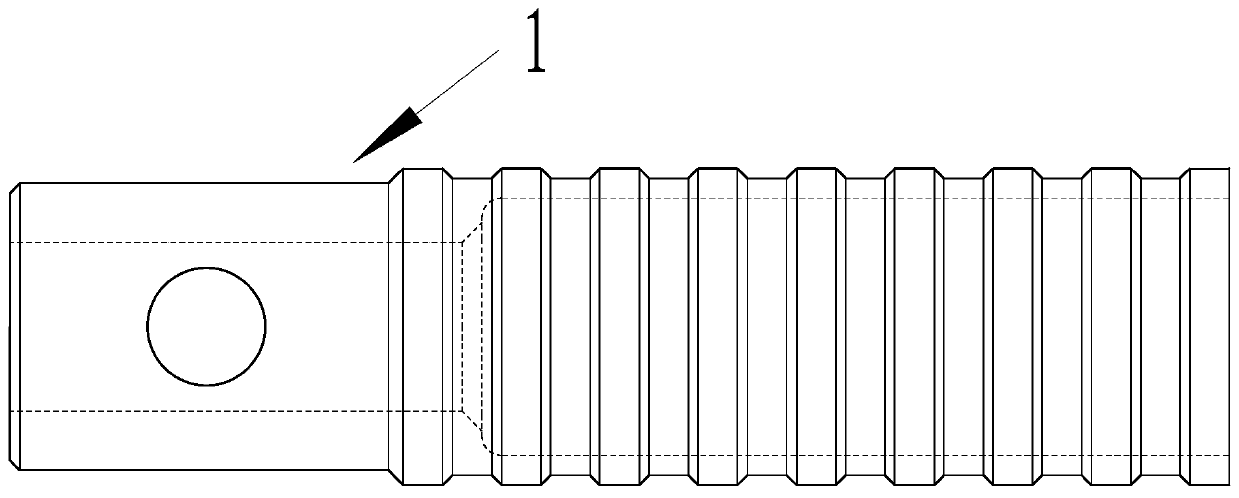
[0032] Such as figure 1 , figure 2 As shown, the composite-metal integrated tie rod of the present invention includes a metal part 1 and a composite material part 2. One end of the metal part is a connecting functional area, and the other end is an anti-slip embedded area. A through hole is provided in the middle of the connecting functional area. It is used to connect with other components during installation; the outer surface of the anti-slip pre-embedded area is wavy and contains several annular grooves. The cross section of the groove is an inverted isosceles trapezoid, and the angle between the bottom and the waist is 135 degrees. The anti-slip pre-embedded area is integrally formed and connected with the composite material component 2 .

[0033] Such as Figure 4 As shown, a composite metal tie rod integrated molding method of the ...


PUM


Abstract

The invention discloses a composite material metal integrated pull rod and a forming method thereof. The pull rod comprises a metal part and a composite material part; one end of the metal part is a connecting function area, and the other end of the metal part is a slippage-preventing pre-embedding area; the outer surface of the slippage-preventing pre-embedding area is wavy and contains a plurality of annular grooves; the section of each groove is an inverted isosceles trapezoid; the slippage-preventing pre-embedding area and the composite material part are integrally formed and connected. During formation, carbon fiber braided fabric prepreg is paved at the periphery of the pre-embedding area alternately, unidirectional belt prepreg is used for winding the wave trough position to perform enhancement, and a hot-pressing tank is used for pressurizing to perform curing molding. The integrated pull rod is simple in structure, light in weight, high in structural strength and high in fatigue resistance, and can serve as a main bearing structural component.

Description

technical field [0001] The invention relates to a composite-metal integrated tie rod and a forming method thereof, belonging to the field of unmanned aerial vehicles. Background technique [0002] With the development of composite materials, the application proportion of composite materials in drones is getting higher and higher, and it has gradually become the main load-bearing material of drone structures. Metal materials have good machining properties and are suitable for structural connections. Therefore, applying composite materials to load-bearing parts and metal materials to connecting parts has become the main direction of UAV structural design. [0003] In structural design, it is inevitable that composite materials will be connected with metal parts, and the connection will become the weak link of the overall structure. In the prior art, glue joints, mechanical joints and hybrid joints are mostly used for the connection of composite materials and metals. [0004...

Claims


Application Information

Patent Timeline
Patent Type & Authority Patents(China)
IPC IPC(8): B64C1/26B29C53/60B29C53/84B29C53/26B29L31/06B29L16/00
Inventor 徐涛陈志平王广博
Owner CHINA ACAD OF AEROSPACE AERODYNAMICS
Learn More