Variable swept wing fighter plane

A technology of swept wings and fighter jets, which is applied in the field of variable swept wings fighters, can solve the problems of easy stall, inability to make full use of swept wings and forward swept wings, and achieve the effects of improving stability, strengthening combat capabilities, and reducing drag

Pending Publication Date: 2017-05-31
李俊孝
View PDF7 Cites 1 Cited by
  • Summary
  • Abstract
  • Description
  • Claims
  • Application Information

AI Technical Summary

Problems solved by technology

[0003] The vast majority of fighter wings in active service are fixed-swept wings or forward-swept wings, which cannot make full use of the advantages of high-speed cruise of the swept-wing wing and good low-speed maneuverability of the forward-swept wing
The problem with the swept wing is that the airflow will accumulate to the outside, and when the angle of attack increases, the outside is easy to stall, and it is easy to stall on one side first, and it is easy to enter the spiral

Method used


Image

  • Variable swept wing fighter plane
  • Variable swept wing fighter plane
  • Variable swept wing fighter plane

Examples


Embodiment Construction

[0021] The technical solution of this patent will be further described in detail below in conjunction with specific embodiments.

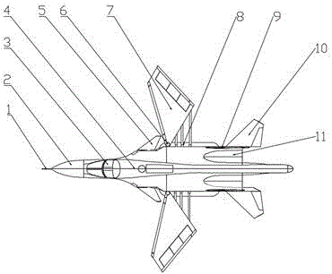
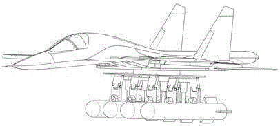
[0022] see Figure 1-9 , a variable-sweep wing fighter, comprising a fuselage, the front end of the fuselage is provided with a radome 2, the front end of the radome 2 is provided with a pitot tube 1, and the interior of the fuselage at the rear end of the radome 2 is provided with a cockpit 3 , the top of the fuselage on the rear side of the cockpit 3 is provided with a dorsal fin 4, the side positions of the fuselage on both sides of the dorsal fin 4 are provided with a canard 5, and the rear side of the canard 5 is provided with a variable swept wing 7, and the variable swept wing The fuselage tail both sides of 7 rear sides are provided with empennage 10, and the fuselage tail between two empennages 10 is provided with tail spray 11, is also provided with vertical tail 9 on the fuselage between tail spray 11 and empennage 10; Variable swept wi...


PUM


Abstract

The invention discloses a variable swept wing fighter plane. The variable swept wing fighter plane comprises a plane body; a radar radome is arranged at the front end of the plane body; an airspeed tube is arranged at the front end of the radar radome; a cockpit is arranged in the part, positioned at the rear end of the radar radome, in the plane body; a dorsal fin is arranged the part, on the rear side of the cockpit, at the top of the plane body; canard wings are arranged in parts, positioned on two sides of the dorsal fin, of side edge positions of the plane body; variable swept wings are arranged on the rear sides of the canard wings; tail wings are arranged on parts, positioned on the rear sides of the variable swept wings, of two sides of the tail part of the plane body; a tail jet is arranged at the tail part, between the two tail wings, of the plane body; a vertical tail is also arranged onthe plane body part between the tail jet and the tail wings; wing roots, leading edge flaps and trailing edge flaps are arranged on the variable swept wings; the leading edge flaps and leading edge slats are connected with each other and are on the same straight line; and spoilers are arranged on the variable swept wings on the internal sides of the trailing edge flaps. The variable swept wing fighter plane has the advantages that the commissioned swept wing fighter plane can enter a swept forward wing during fighting to enhance the near-space fighting capacity of the fighter plane; and moreover, missiles can be launched from multiple angles by using a rotatable telescopic missile pylon so that the fighting capacity of the fighter plane is greatly enhanced.

Description

technical field [0001] The invention relates to the field of defense technical equipment, in particular to a variable-sweep wing fighter. Background technique [0002] Fighter aircraft, also known as fighter aircraft, are military aircraft used to destroy enemy aircraft and other flying air strike weapons in the air. During World War II, it was widely known as a destroyer. The main task of fighters is to engage in air combat with enemy fighters to gain air superiority (air supremacy). The second is to intercept enemy bombers, attack aircraft and cruise missiles, and it can also carry a certain number of ground attack weapons to perform ground attack missions. [0003] Most of the fighter wings in active service are fixed-swept wings or forward-swept wings, which cannot take full advantage of the high-speed cruise advantages of the swept-wing wings and the low-speed maneuverability of the forward-swept wings. The problem with the swept wing is that the airflow will accumul...

Claims


Application Information

Patent Timeline
Patent Type & Authority Applications(China)
IPC IPC(8): B64C3/40B64C3/58B64C9/08B64C9/14B64D7/08B64D1/06
CPCB64C3/40B64C3/58B64C9/08B64C9/14B64D1/06B64D7/08
Inventor 李俊孝
Owner 李俊孝
Why Eureka
Try Eureka