Rubber pipe discharging device

A rubber hose and conduit technology, applied in the field of rubber hose feeding device, can solve problems such as difficult to guarantee quality, slow running speed, inaccurate joint detection, etc., and achieve the effect of reasonable structural design, high production efficiency, and not easy to slip

Active Publication Date: 2017-05-31
WUHU TONHE AUTOMOBILE FLUID SYST
9 Cites 0 Cited by

AI-Extracted Technical Summary

Problems solved by technology

Rubber has high elastic deformation, and it is easy to deform due to external force during the blanking process to increase the error
[0004] In addition, the traditional rubber hose feeding device uses screw drive to make the equipment run at a slower speed and lower in efficie...

Method used

[0027] The feeding tray 1 includes a rotating disc and a support, and the support is provided with a drive motor 101 that drives the rotating disc to rotate. Among them, the bracket is a triangular frame, and the rotating plate is set at an inclination, which is convenient for loading materials. The driving motor drives the rotating plate to rotate, and the end of the rubber hose is not easy to pull off.
[0028] The material rack 2 is a frame structure, and the middle part of the material rack is provided with intermediate rollers 202, and the material rack bottom is provided with side rollers 203 on both sides of the intermediate rollers. The feeding hose first passes through the side roller at the bottom of one side, then passes through the middle roller, and finally passes through the side roller at the bottom of the other side, so that the hose can be straightened. The feeding rack is provided with an auxiliary motor 201 for driving the intermediate rollers to prevent the rubber hose from slipping.
[0031] The pulley set includes a row of pulleys 302 above and a pulley below. The pulley below is a driving pulley, and the driving pulley is connected to the motor on the frame. One set of positioning wheels ...

Abstract

The invention discloses a rubber pipe discharging device. The rubber pipe discharging device comprises a feeding disc and a rubber pipe cut-off and discharging machine which are sequentially arranged. The rubber pipe cut-off and discharging machine comprises a conveying wheel set, a rubber pipe cut-off mechanism and a guide pipe for a rubber pipe to penetrate. The conveying wheel set is internally provided with a rubber pipe penetrating gap. The guide pipe comprises two sections, a cutter is correspondingly arranged between the two sections, an opening is formed in the pipe wall of the guide pipe in the axial direction, and the part, corresponding to the opening, of the guide pipe is provided with a laser sensor used for detecting the end portion of the rubber pipe. The rubber pipe discharging device is reasonable in structural design, feeding is conducted through double power sources, and it is guaranteed that the end portion of the rubber pipe is not prone to being pulled; belt conveying is adopted, the contact area is large, skidding is not likely to happen, and the rubber pipe cannot be subjected to extrusion deformation; the laser sensor is used for controlling the cut-off length of the rubber pipe, precision is high, and accuracy and reliability are achieved; and automatic rubber pipe cutting-off and discharging are achieved, the production efficiency is high, and cost is reduced.

Application Domain

Filament handling

Technology Topic

EngineeringLaser sensor +3

Image

  • Rubber pipe discharging device
  • Rubber pipe discharging device
  • Rubber pipe discharging device

Examples

  • Experimental program(1)

Example Embodiment

[0024] The specific embodiments of the present invention will be described in further detail below through the description of the embodiments with reference to the accompanying drawings.
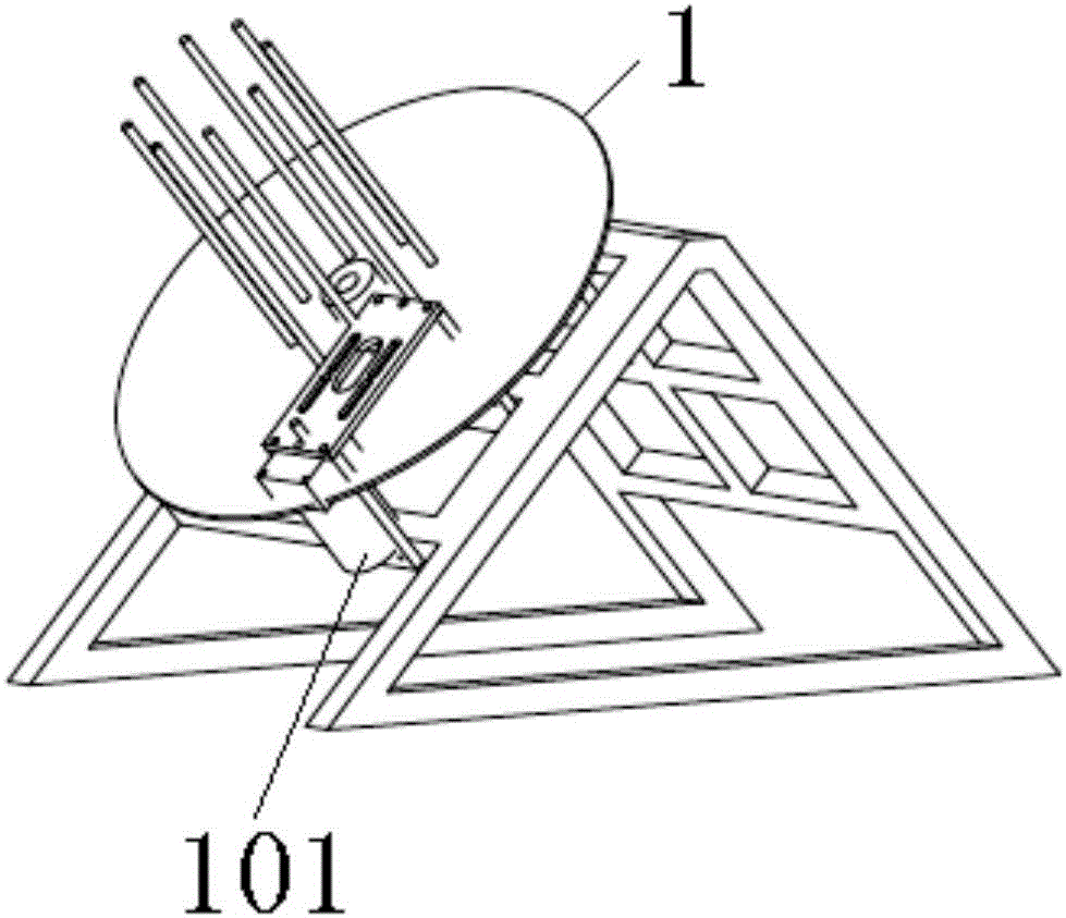
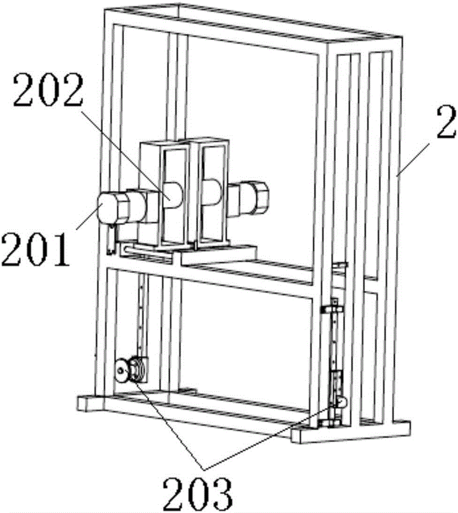
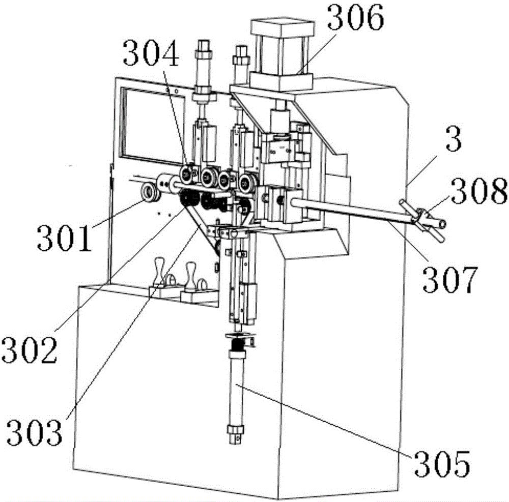
[0025] like Figure 1 to Figure 3 As shown, the rubber tube feeding device includes a feeding tray 1 and a feeding rack 2 arranged in sequence, and a rubber tube cutting and feeding machine.
[0026] The coiled rubber hose is sleeved on the feeding tray 1, and transits through the feeding rack 2 in the middle. The rubber hose is fed to the rubber hose cutting and unloading machine, and the rubber hose is cut off by the rubber hose cutting and unloading machine, and the material is automatically unloaded.
[0027] The feeding plate 1 includes a rotating plate and a bracket, and the bracket is provided with a driving motor 101 for driving the rotating plate to rotate. Among them, the bracket is a triangular frame, the rotating plate is inclined, which is convenient for feeding, and the driving motor drives the rotating plate to rotate, and the end of the rubber tube is not easy to pull off.
[0028] The feeding rack 2 is a frame structure, the middle of the feeding frame is provided with a middle roller 202, and the bottom of the feeding frame is provided with side rollers 203 on both sides of the middle roller. The feeding hose first passes through the side roller at the bottom of one side, then passes through the middle roller, and finally passes through the side roller at the bottom of the other side, so that the hose can be straightened. The feeding rack is provided with an auxiliary motor 201 for driving the intermediate roller to prevent slippage of the feeding of the rubber tube.
[0029] The rubber hose cutting and unloading machine includes a frame 3, a conveying roller set, a rubber hose cutting mechanism, and a conduit 307 for the rubber hose to pass through.
[0030] The frame 3 is provided with a support wheel 301 in front of the conveying roller group. The conveying roller group is provided with a gap through which the rubber hose passes. The conveying roller group includes a belt pulley group located below. A set of positioning wheels 304 are provided, and a gap through which the rubber tube passes is set between the positioning wheels and the belt.
[0031] The pulley set includes a row of pulleys 302 at the top and a pulley at the bottom. The pulley at the bottom is a driving pulley, and the driving pulley is connected to the motor provided on the frame. A set of positioning pulleys is also a set of positioning pulleys arranged side by side. The number of positioning pulleys is the same as that of a row of pulleys placed side by side. The upper and lower belts are arranged correspondingly. The contact area between the belt and the hose is large, and the hose is not easy to slip and deform.
[0032] The frame 1 is provided with a positioning cylinder 306 for driving the positioning wheel 304 to ascend and descend. Through the positioning cylinder, the height of the positioning wheel can be adjusted, and the gap between the positioning wheel and the lower belt can be adjusted to adapt to the feeding and cutting of different sizes of rubber hoses.
[0033] The conduit 307 includes two sections, and a cutter is correspondingly arranged between the two sections. The frame is provided with a working cylinder that drives the cutter to move, and the cutter moves downward to cut off the rubber tube directly below the cutter.
[0034] The pipe wall of the conduit 307 is provided with an opening along the axial direction, and a laser sensor 308 for detecting the end of the rubber tube is provided on the conduit corresponding to the opening. The position of the laser sensor 308 on the catheter can be adjusted along the axial direction of the catheter to meet the cutting requirements of different hose lengths. According to the position of the knife edge as the 0 point, that is the reference point, the distance from the reference point to the laser sensor is the length of the cut hose.
[0035] The cutting length of the hose is controlled by the laser sensor, with high precision, accurate and reliable; the automatic cutting and blanking of the hose is realized, the production efficiency is high, and the cost is reduced.
[0036] The conduit 307 is provided with two openings corresponding to both sides of the cutter, and corresponding openings are provided with a pen for marking the hose. Specifically, the lower part of the frame is provided with a lifting cylinder, the end of the piston rod of the lifting cylinder is provided with a horizontal plate, and both ends of the horizontal plate are provided with a pen, each pen corresponds to an opening position on the guide tube, and the lifting cylinder drives the pen to move up and down. , Mark the end of the hose as the installation benchmark for the hose connector to improve the installation quality.
[0037] The present invention has been exemplarily described above in conjunction with the accompanying drawings. Obviously, the specific implementation of the present invention is not limited by the above manner, as long as various insubstantial improvements made by the concept and technical solutions of the present invention are adopted, or the If the concept and technical solutions of the present invention are directly applied to other occasions, they all fall within the protection scope of the present invention.

PUM

no PUM

Description & Claims & Application Information

We can also present the details of the Description, Claims and Application information to help users get a comprehensive understanding of the technical details of the patent, such as background art, summary of invention, brief description of drawings, description of embodiments, and other original content. On the other hand, users can also determine the specific scope of protection of the technology through the list of claims; as well as understand the changes in the life cycle of the technology with the presentation of the patent timeline. Login to view more.

Similar technology patents

Long-rubber-barrel differential pressure type water filling packer capable of washing well

Owner:DRILLING TECH DEV CO LTD OF TIANJIN DAGANG OILFIELD PETROLEUM ENG INST +1

Burr polish-grinding device of metal pipe inner wall

ActiveCN109108750AReasonable structural designHigh stability and linkage
Owner:嘉兴尚坤科技有限公司

Profile auto-laminating device

InactiveCN105857716AReasonable structural designsmall fluctuation
Owner:芜湖海杉新材料科技有限公司

Classification and recommendation of technical efficacy words

  • increase contact surface
  • Reasonable structural design

Wastewater photocatalytic treatment apparatus

InactiveCN106006833Aincrease contact surfaceIncrease catalytic time
Owner:NANJING INST OF ENVIRONMENTAL SCI MINIST OF ECOLOGY & ENVIRONMENT OF THE PEOPLES REPUBLIC OF CHINA

Ornamental Attachment Device

InactiveUS20140298625A1increase contact surface
Owner:GUAL JAIME BACH +1

Novel wire clamping disc

Owner:STATE GRID SHANDONG ELECTRIC POWER

Bolt machining all-in-one machine

Owner:ANHUI LIUFANG ZHONGLIAN MECHANICAL SHARE

Internet of things multifunctional intelligent cabinet

PendingCN107622595AReasonable structural designEasy to sell automatically
Owner:王飞天

Automatic operation device of upper drill floor and lower drill floor of drill rod

InactiveCN102230364AReasonable structural designEasy and reliable operation
Owner:SHENGLI OIL FIELD HAISHENG ENVIRONMENTAL PROTECTION ENG
Why Eureka
Try Eureka