Crane trolley adopting hydraulic lifter for lifting loads

A hydraulic lifting and crane technology, applied in the direction of load block, load hanging components, traveling mechanism, etc., can solve the problems of long-term inspection and maintenance, low frequency of use, complex structure, etc., achieve convenient disassembly and maintenance, and save costs , the effect of simple structure

Inactive Publication Date: 2017-05-31
DALIAN HUARUI HEAVY IND GRP CO LTD
View PDF8 Cites 1 Cited by
  • Summary
  • Abstract
  • Description
  • Claims
  • Application Information

AI Technical Summary

Problems solved by technology

The mechanism contains many parts and has a complex structure. During the construction of the entire power station, the installation trolley is only used for the installation of

Method used


Image

  • Crane trolley adopting hydraulic lifter for lifting loads
  • Crane trolley adopting hydraulic lifter for lifting loads

Examples


Embodiment Construction

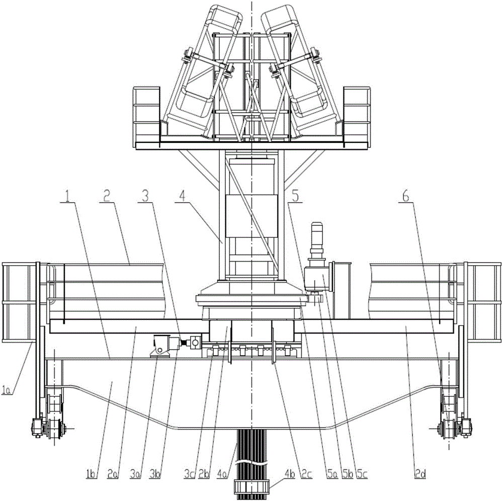
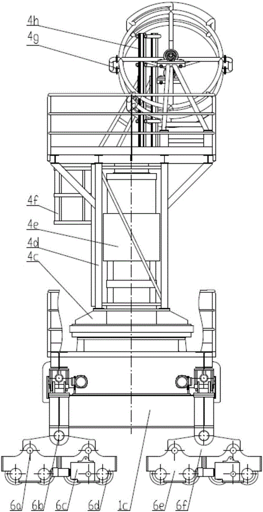
[0040] Such as figure 1 and figure 2 The shown crane trolley adopts a hydraulic hoist to lift loads, including: a lower frame 1, an upper frame 2, a translation mechanism 3, a lifting mechanism 4, a rotation mechanism 5 and an operating mechanism 6;

[0041] The running mechanism 6 drives the trolley to reciprocate along the direction of the track, and the running mechanism 6 is installed at both ends of the lower frame 1;

[0042] The translation mechanism 3 is arranged in the upper middle area of ​​the lower frame 1, and the translation mechanism 3 carries the upper frame 2, the lifting mechanism 4 and the rotation mechanism 5;

[0043] The rotating mechanism 5 is arranged between the upper frame 2 and the lifting mechanism 4 and fixed on the upper frame 2;

[0044] The lifting mechanism 4 is fixed on the rotating mechanism 5, and the rotating mechanism 5 can drive the lifting mechanism 4 to rotate 360 ​​degrees;

[0045] The lower frame 1 includes: a boarding ladder 1a,...


PUM


Abstract

The invention discloses a crane trolley adopting a hydraulic lifter for lifting loads. The crane trolley comprises a lower trolley frame, an upper trolley frame, a horizontal-moving mechanism, a lifting mechanism, a rotating mechanism and running mechanisms. The running mechanisms drive the whole trolley to conduct reciprocating movement in the rail direction. The running mechanisms are installed at the lower ends of the lower trolley frame. The horizontal-moving mechanism is arranged in the middle area of the upper portion of the lower trolley frame. The horizontal-moving mechanism bears the upper trolley frame, the lifting mechanism and the rotating mechanism. The rotating mechanism is arranged between the upper trolley frame and the lifting mechanism and is fixed to the upper trolley frame. The lifting mechanism is fixed above the rotating mechanism. The rotating mechanism can drive the lifting mechanism to rotate by 360 degrees. By means of the above technical scheme, the overall structural division of the crane trolley is definite, the structure is simple, and manufacturing, installing, demounting and later-period maintaining are facilitated.

Description

technical field [0001] The invention relates to the field of crane equipment, in particular to a crane trolley that adopts a hydraulic hoist to lift and lower loads. Background technique [0002] During the construction of the nuclear power plant, the installation of large parts such as the pressure vessel of the reactor building relies on the installation trolley on the ring crane. The structure of the conventional installation trolley is the same as that of the working trolley, including the lifting mechanism, the operating mechanism and the trolley frame. The lifting mechanism includes Motors, brakes, couplings, reducers, reel sets, wire ropes, pulley sets, hook sets and other components. The mechanism contains many parts and has a complex structure. During the entire construction period of the power station, the installation trolley is only used for the installation of large parts such as pressure vessels, and the frequency of use is low. Due to the large number of parts...

Claims


Application Information

Patent Timeline
IPC IPC(8): B66C11/08B66C9/10
CPCB66C11/08B66C9/10
Inventor 张金晶徐宏伟田树海苏冬
Owner DALIAN HUARUI HEAVY IND GRP CO LTD
Why Eureka
Try Eureka