
Upper spindle rod suspended rod flyer with bobbin hanging unloading mechanism

A bobbin and flyer technology, applied in textiles and papermaking, etc., can solve the problems of declining efficiency, inconsistency in saving resources, protecting the environment and low-carbon circular development, and achieving the effects of saving resources, improving labor productivity, and having a simple structure

Inactive Publication Date: 2017-05-31
无锡诚本纺机有限公司
View PDF7 Cites 2 Cited by
  • Summary
  • Abstract
  • Description
  • Claims
  • Application Information

AI Technical Summary

Problems solved by technology

If the spinning mills that use the upper spindle suspended spindle roving frame account for more than 95% of the total number of roving frames to realize automatic doffing, they need to eliminate the old machine first, and then purchase an expensive lower spindle suspended spindle automatic collective doffing roving frame (60 10,000 / unit), which is not in line with the basic national policy of resource conservation, environmental protection, and low-carbon circular development
It is also inconsistent with the current national conditions that domestic textile enterprises are affected by international and domestic dual pressures and their own structural adjustments, and their profits are declining, and they are unable to carry out expensive equipment updates. Yarn device is very necessary and urgent

Method used

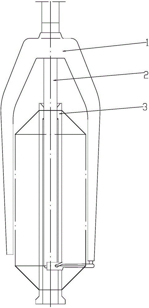

Image

  • Upper spindle rod suspended rod flyer with bobbin hanging unloading mechanism
  • Upper spindle rod suspended rod flyer with bobbin hanging unloading mechanism

Examples


Embodiment Construction

[0013] Below the present invention will be further described in conjunction with the embodiment in the accompanying drawing:

[0014] Such as Figure 1~2 As shown, the present invention mainly includes a flyer main body 1, a hollow spindle bar 2 and a hollow bobbin 3, the flyer main body 1 is sleeved on the hollow spindle bar 2, a hollow bobbin tube 3 is sleeved on the hollow spindle bar 2, and the hollow bobbin tube 3. It can perform relative rotational movement and up-and-down reciprocating movement along the hollow spindle bar 2.

[0015] The hollow spindle bar 2 is provided with a left and right through locking hole 9 , and the inner side wall of the hollow spindle bar 2 is connected to the hexagonal claw 4 through the horizontal pin 5 .

[0016] The hexagonal claw 4 includes a central fixed block 4.1 with a square structure, and two claw bodies 4.2 are symmetrically arranged on the left and right ends of the central fixed block 4.1.

[0017] The hexagonal claw 4 can rot...


PUM


Abstract

The invention relates to an upper spindle rod suspended rod flyer, in particular relates to an upper spindle rod suspended rod flyer with a bobbin hanging unloading mechanism, and belongs to the technical field of textile equipment. The upper spindle rod suspended rod flyer comprises a flyer main body, a hollow spindle rod and a hollow bobbin, the hollow bobbin is arranged in a sleeving mode on the hollow spindle rod, and the hollow bobbin can do relative rotating movements and up and down reciprocal movements following the hollow spindle rod. Two claw bodies of a hexagon claw can extend out of a locking hole when rotating to a level position, so that the hollow bobbin is hung on the hollow spindle rod; the two claw bodies of the hexagon claw retract in the locking hole when rotating to a vertical position, so that the hollow bobbin can slide up and down along the hollow spindle rod. The upper spindle rod suspended rod flyer is an essential component for the achieving of intelligentized production of spindle rod suspended rod flyer coarse spinners, the labor intensity of the operation workers can be lowered, the labor production rate of the coarse spinners is increased, and the cost-lowering and effect-increasing result can be achieved.

Description

technical field [0001] The invention relates to an upper spindle rod suspended spindle flyer, in particular to an upper spindle rod suspended spindle flyer with a bobbin tube hanging and unloading mechanism, which belongs to the technical field of textile equipment. Background technique [0002] Since the 1990s, my country's cotton spinning ring spinning system began to use a large number of suspended spindle roving frames. For more than 20 years, single-motor-driven roving frames (iron gun machines) and multi-motor-driven roving frames (computer machines) have been equipped with upper spindles and suspended spindles, and adopt "semi-automatic doffing": when the roving reaches the set winding length , the roving frame automatically stops running, the lower dragon tendon lowers to the doffing position, the worker takes out the full bobbin and loads it on the roving transport vehicle, then puts the empty bobbin on the bobbin seat, presses the lower dragon tendon up button to m...

Claims


Application Information

Patent Timeline
Patent Type & Authority Applications(China)
IPC IPC(8): D01H7/26D01H7/42
CPCD01H7/26D01H7/42
Inventor 袁景山李毕俊
Owner 无锡诚本纺机有限公司
Learn More