Numerical control pipe bending machine capable of dynamically correcting hole sites through visual inspection and pipe bending method

A dynamic correction and visual inspection technology, applied in metal processing, metal processing equipment, manufacturing tools, etc., can solve the problems of easy occurrence of eccentricity and inclination, circumferential position error of single hole, difficulty in pipe docking and assembly, etc., to achieve clamping The effect of large force, improving accuracy and avoiding pipe flange damage

Active Publication Date: 2021-07-16
JIANGYIN HONGYE MECHANICAL
View PDF5 Cites 3 Cited by
  • Summary
  • Abstract
  • Description
  • Claims
  • Application Information

AI Technical Summary

Problems solved by technology

[0008] First, because there is a large gap between the flange and the pipe, the flange and the pipe are prone to eccentricity and inclination during assembly, so that the position of the bolt holes on the flange, especially the circumferential position, is relatively large relative to the center of the pipe. Large offset; if only single hole positioning is used to determine the circumferential position of the flange, it will lead to a large circumferential position error in another single hole arranged at 180° relative to the single hole, resulting in subsequent three-dimensional bending of the pipe. Pipeline butt joint assembly is difficult, or even impossible to assemble
[0009] Second, the rotation mechanism of the servo trolley of the pipe bending machine also has a certain rotation error, which will also cause the circumferential error of the bolt hole position on the flange relative to the three-dimensional bending pipe, resulting in difficulties in the butt joint assembly of the pipeline, and even failure to assemble Phenomenon

Method used


Image

  • Numerical control pipe bending machine capable of dynamically correcting hole sites through visual inspection and pipe bending method
  • Numerical control pipe bending machine capable of dynamically correcting hole sites through visual inspection and pipe bending method
  • Numerical control pipe bending machine capable of dynamically correcting hole sites through visual inspection and pipe bending method

Examples


Embodiment 1

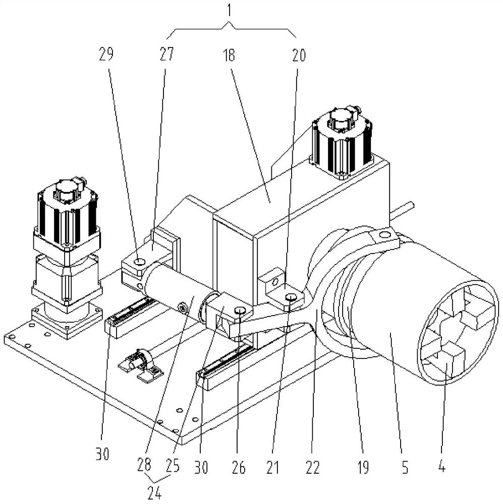
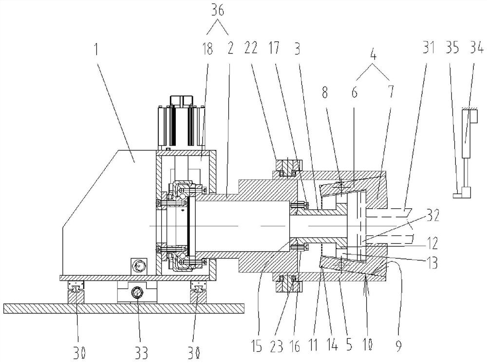
[0053] Such as Figures 1 to 4 Shown is an embodiment of a digitally controlled pipe bender of the present invention that dynamically corrects hole positions through visual inspection, including a pipe bender servo trolley 1, a trolley rotation mechanism 36 arranged on the pipe bender servo trolley 1, and a connecting The self-centering clamping mechanism 37 used to clamp the flanged pipeline on the trolley rotating mechanism 36 is arranged beside the self-centering clamping mechanism 37 for detecting the flanged pipeline A visual recognition device for flange holes; the visual recognition device includes a camera 35 and a visual recognition system connected to the camera 35, and the visual recognition system and the camera 35 are respectively connected to the control system of the numerically controlled pipe bender.

[0054] Preferably, the camera 35 is set on the lifting mechanism 34, and the lifting mechanism 34 is connected to the control system of the numerically controll...

Embodiment 2

[0056] A pipe bending method using a digitally controlled pipe bender for dynamically correcting hole positions through visual detection in Embodiment 1, comprising the following steps:

[0057] Step 1. Clamping of the flanged pipeline: the flanged pipeline 38 is clamped by the self-centering clamping mechanism 37 of the servo trolley 1 of the pipe bender;

[0058] Step 2. Dynamic correction of the initial position of the flange hole after clamping, which includes the following steps in turn:

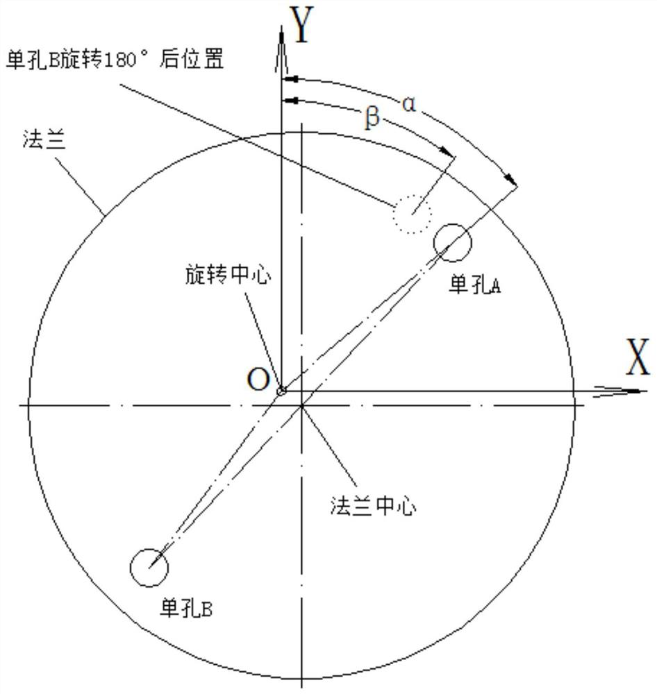
[0059] (1) Flange single hole identification: set the camera 35 coordinate system, and identify one of the single holes A and its position on the pipe flange 32 with the flanged pipeline 38 through the visual identification device;

[0060] (2) Rotation center position setting: the trolley rotation mechanism 36 rotates, drives the flanged pipeline 38 on the self-centering clamping mechanism 37 to rotate together, and rotates the single hole A on the pipe flange 32 to multiple At differ...


PUM


Abstract

The invention relates to the technical field of pipe bending machines, in particular to a numerical control pipe bending machine capable of dynamically correcting hole sites through visual inspection and a pipe bending method. The numerical control pipe bending machine comprises a pipe bending machine servo trolley, a trolley rotating mechanism arranged on the pipe bending machine servo trolley, a self-centering clamping mechanism connected to the trolley rotating mechanism and used for clamping a pipeline with a flange, and a visual identification device arranged beside the self-centering clamping mechanism and used for detecting the flange hole sites on the pipeline with the flange. The visual identification device comprises a camera and a visual identification system connected with the camera, and the visual identification system and the camera are respectively connected with a control system of the numerical control pipe bending machine. The bending precision of the pipeline with the flange is improved.

Description

technical field [0001] The invention relates to the technical field of pipe bending machines, in particular to a numerically controlled pipe bending machine and a pipe bending method for dynamically correcting hole positions through visual detection. Background technique [0002] CNC pipe bending machine is an automatic equipment that bends and deforms pipes into bent pipes. [0003] In the prior art, a typical numerically controlled pipe bender includes a pipe bender host (servo trolley). It mainly includes a numerically controlled rotating mechanism driven by a reduction transmission mechanism, and a chuck for clamping pipes is arranged on the numerically controlled rotating mechanism. During bending, the pipe is clamped by the chuck, and with the cooperation of the pipe bending mold, the rotation angle and moving distance are controlled by the numerical control system to realize the three-dimensional bending of the pipe. [0004] According to different bending processes...

Claims


Application Information

Patent Timeline
Patent Type & Authority Applications(China)
IPC IPC(8): B21D11/00B21C51/00B21D11/22B21D9/04
CPCB21D11/00
Inventor 赵文寿
Owner JIANGYIN HONGYE MECHANICAL
Why Eureka
Try Eureka