Cast-in-situ support bearing bracket structure for No. 0 segment of large-span rigid-frame continuous girder

A bracket structure and large-span technology, applied in bridges, bridge construction, erection/assembly of bridges, etc., can solve problems such as affecting the construction period and increasing material input, and achieve the effects of convenient installation and dismantling, low cost and fast construction.

Inactive Publication Date: 2017-05-31
CHINA RAILWAY NO 5 ENG GRP +1
View PDF5 Cites 2 Cited by
  • Summary
  • Abstract
  • Description
  • Claims
  • Application Information

AI Technical Summary

Problems solved by technology

[0003] The technical problem to be solved by the present invention is to provide a large-span continuous beam No. 0 section construction cast-in-place support support bracket structure to overcome the limitations of terrain constraints that cannot use floor supports, which often increase material input and affect the construction period.

Method used


Image

  • Cast-in-situ support bearing bracket structure for No. 0 segment of large-span rigid-frame continuous girder
  • Cast-in-situ support bearing bracket structure for No. 0 segment of large-span rigid-frame continuous girder
  • Cast-in-situ support bearing bracket structure for No. 0 segment of large-span rigid-frame continuous girder

Examples


Embodiment Construction

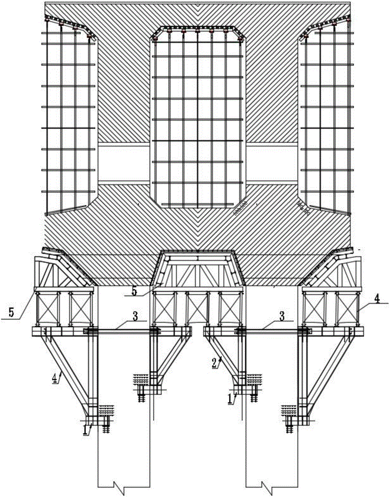
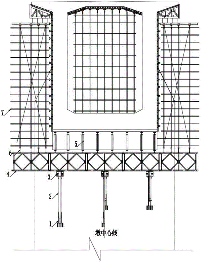
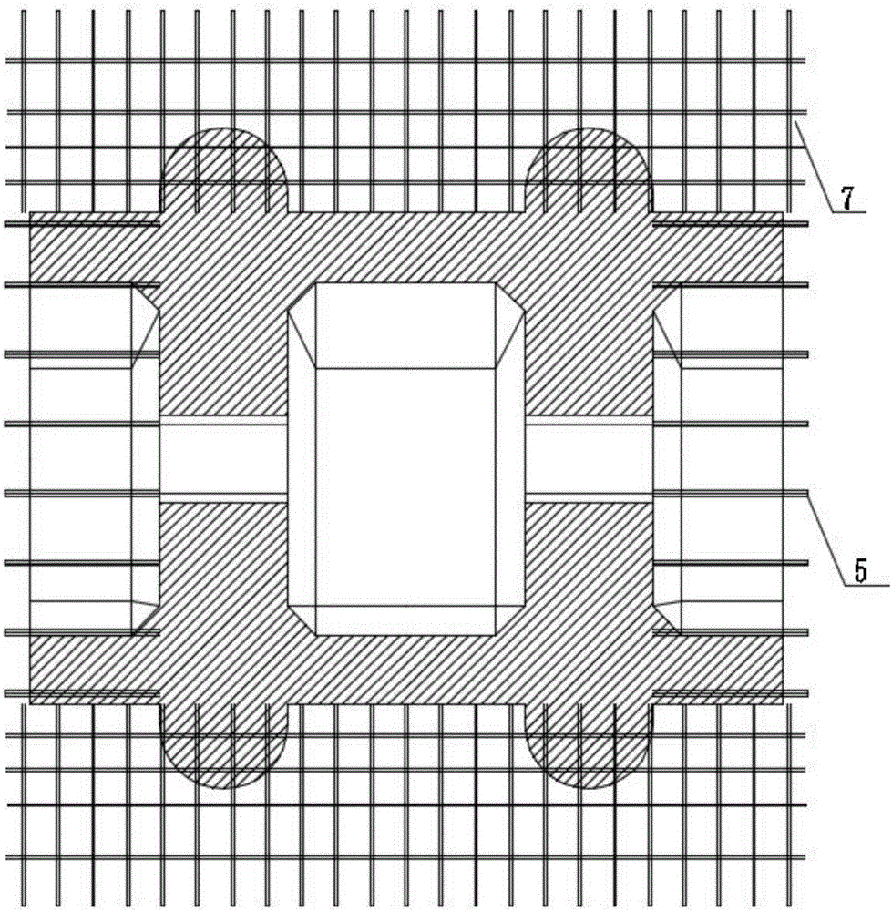
[0015] Embodiment of the present invention: No. 0 section of the continuous beam spanning the expressway and the river section, adopts the combined bracket structure of the prefabricated triangular bracket 2, the steel plate corbel 1 in the pre-buried pier body and the connecting piece 3, and the combined bracket adopts The Bailey beam 4 and the Bailey beam 4 are respectively provided with a truss 5 bearing the load of the bottom plate of the box girder and an I-beam distribution beam 6 bearing the load of the wing plate of the box girder. the whole frame.

[0016] The triangular bracket 2 is welded and rigidly connected to the steel plate corbel 1 inside the pre-embedded pier body.

[0017] The connecting pieces 3 are used to connect the triangular brackets 2 on both sides of the pier body.

[0018] The connecting piece 3 is connected by a 32mm-diameter finish-rolled rebar and prestressed.

[0019] Bailey beam 4 adopts 2 sets of pre-assembled on site, and then the car crane...


PUM

PropertyMeasurementUnit
Diameteraaaaaaaaaa

Abstract

The invention discloses a cast-in-situ support bearing bracket structure for a No. 0 segment of a large-span rigid-frame continuous girder. A combined bracket structure combining prefabricated triangular brackets (2), pre-embedded pier body inner steel plate corbels (1) and connecting pieces (3) is adopted; Bailey beams (4) are arranged on the combined bracket; the Bailey beams (4) are provided with trusses (5) for carrying box girder bottom plates and I-shaped steel distributive girders (6) for carrying box girder flanges; upside down bowl-type full space supports (7) are arranged on the I-shaped steel distributive girders (6) to form an integral structure. By adopting the cast-in-situ support bearing bracket structure for the No. 0 segment of the large-span rigid-frame continuous girder, a cast-in-situ support bearing bracket is designed according to the stress characteristic of the No. 0 segment of the continuous girder, and the brackets are erected segmentally and sequentially, so that the brackets can be assembled and disassembled conveniently, limitations by regions such as river-crossing regions and express ways are broken, the quantity of required brackets is small, and rapid construction and low cost are realized.

Description

technical field [0001] The invention relates to a large-span continuous beam cast-in-place bracket support bracket structure. Background technique [0002] At present, the design of large-span continuous beams in railway construction generally adopts the method of hanging baskets for hanging irrigation. With the increasing number of continuous beams crossing rivers and expressways, it is limited to use floor supports for the construction of No. 0 section. Traditional floor supports have high requirements on the bearing capacity of the foundation and are limited by the terrain. Therefore, the use of floor supports for the construction of No. 0 section of continuous girder bridges when crossing rivers and expressways is restricted, and often cannot meet the construction requirements. Even if conditions permit, floor-mounted supports are used for construction, which has the disadvantages of long construction period, large material consumption, and poor economic benefits. Cont...

Claims


Application Information

Patent Timeline
IPC IPC(8): E01D21/00
CPCE01D21/00
Inventor 宋作栋陈俊龙
Owner CHINA RAILWAY NO 5 ENG GRP
Why Eureka
Try Eureka