
Mass concrete cooling device based on air cooling, construction method and application

A large-volume concrete and cooling device technology, applied in infrastructure engineering, construction, etc., can solve problems such as strong dependence on water resources, waste, and high requirements for pipeline sealing, and achieve low dependence on water resources, simple operation, and geographical location The effect of small constraints

Pending Publication Date: 2017-05-31
中交一公局厦门检测技术有限公司
View PDF6 Cites 14 Cited by
  • Summary
  • Abstract
  • Description
  • Claims
  • Application Information

AI Technical Summary

Problems solved by technology

The technology of water cooling mass concrete is relatively mature, but the application of this method also has certain limitations, such as: strong dependence on water resources, serious waste, and high requirements for pipeline sealing.

Method used


Image

  • Mass concrete cooling device based on air cooling, construction method and application
  • Mass concrete cooling device based on air cooling, construction method and application
  • Mass concrete cooling device based on air cooling, construction method and application

Examples


Embodiment 1

[0031] A bridge approach bridge cap

[0032] 1) Project overview

[0033] The main bridge of a certain bridge has a total length of 848m and is a seven-span, double-tower and double-cable-plane symmetrical mixed-girder cable-stayed bridge. The bridge has 8 auxiliary transition pier caps. All the caps are made of C40 marine concrete, and the caps of the auxiliary transition piers are poured and formed at one time.

[0034] 2) Construction status

[0035] The auxiliary transitional pier cap adopts the construction technology of wind-cooled mass concrete, and the one-time pouring construction was completed from late May to early June 2016. The ambient temperature on site is 25°C to 35°C. The construction on site is in good condition. Long-term observation shows that there is no crack in the concrete, and the temperature field has been scientifically and effectively analyzed, and the entire construction process has achieved the expected effect. Its successful temperature contr...

Embodiment 2

[0048] A bridge main line abutment

[0049] 1) Project overview

[0050] The main span of a certain bridge is a single-span simply supported steel box girder suspension bridge, and approach bridges are set on both banks, with a total length of 2030m. The construction of the present invention relies on the abutment, which is the connecting part of the bridge and road, and has a large volume, and is formed by one-time pouring of C35 concrete.

[0051] 2) Construction status

[0052] The abutment adopts wind-cooled mass concrete construction technology, and the construction was completed from the end of November to mid-December 2015. The ambient temperature is about 8°C to 15°C. The site construction is in good condition and there are no cracks, which has been agreed by the owner and the supervisor. praise.

[0053] 3) The specific construction method is as follows:

[0054] ① First, simulate the pipeline layout and overall stress of the building to be constructed, and determ...


PUM

PropertyMeasurementUnit
Thermal conductivityaaaaaaaaaa
Wall thicknessaaaaaaaaaa

Abstract

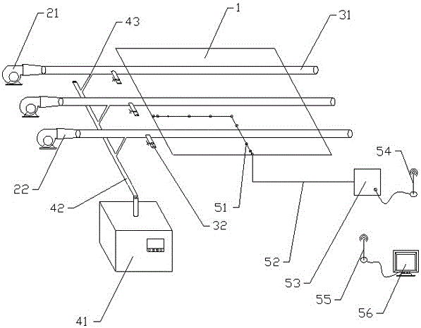
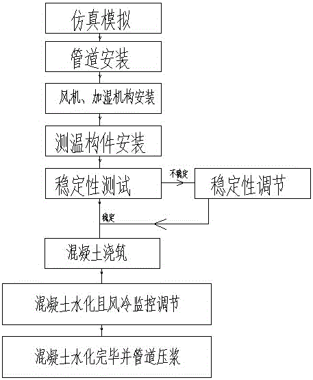
The invention belongs to the technical field of civil construction, and particularly relates to a mass concrete cooling device based on air cooling, a construction method and application. In order to overcome the technical defects in mass concrete water cooling in construction, the brand-new mass concrete temperature cracking prevention and control technology supplementation is provided; and at the specific air speed, cooling air and fog are mixed to enter a cooling pipe, made of high-heat-conduction-coefficient materials, in the concrete, heat exchange is carried out, heat continuously accumulated in a ventilating duct is brought out continuously, and the temperature inside the concrete is decreased. The mass concrete cooling device and the construction method are successfully applied to two practical projects, zero crack control of the mass concrete cooling device and the construction method in practical project construction is achieved, and the better application effects are obtained.

Description

technical field [0001] The invention belongs to the technical field of civil engineering, and in particular relates to an air-cooled mass concrete cooling device, construction method and application. Background technique [0002] With the continuous application of mass concrete in modern bridge engineering construction, my country's bridge construction is gradually moving towards the direction of large spans. Compared with ordinary reinforced concrete structures, mass concrete has the advantages of large thickness and section size, and a large amount of concrete. The engineering conditions are complex, the integrity is good, and the construction technology requirements are high. During the hardening process of concrete, a large amount of heat of hydration will be released, and the heat will continue to accumulate inside the structure, causing the internal temperature of the structure to rise continuously. Due to the better heat dissipation on the surface, the temperature rise...

Claims


Application Information

Patent Timeline
IPC IPC(8): E02D15/02
CPCE02D15/02E02D2250/0023
Inventor 黄斌谢生华龚明子康梦安周世康袁忠标王奎
Owner 中交一公局厦门检测技术有限公司
Learn More