Method and device of automatically paving wall body mosaic pattern by utilizing small tiles

A mosaic and tile technology, applied in the field of architectural decoration, can solve the problems of pasting quality differences, heavy workload, complicated procedures, etc., achieve high placement efficiency, reduce labor costs, and ensure placement quality standards

Inactive Publication Date: 2017-05-31
XUCHANG UNIV
View PDF7 Cites 7 Cited by
  • Summary
  • Abstract
  • Description
  • Claims
  • Application Information

AI Technical Summary

Problems solved by technology

Traditional ceramic chip mounting requires skilled workers to complete manually, the process is complicated, the workload is heavy, and there is no uniform quality standard for pasting; at the same time, in the ceramic chip mounting project completed by multiple people, due to the difference in experience and technology of each person, it is easy

Method used


Image

  • Method and device of automatically paving wall body mosaic pattern by utilizing small tiles
  • Method and device of automatically paving wall body mosaic pattern by utilizing small tiles
  • Method and device of automatically paving wall body mosaic pattern by utilizing small tiles

Examples


Embodiment 1

[0060] Example 1: Wall tile grid mosaic pattern placement

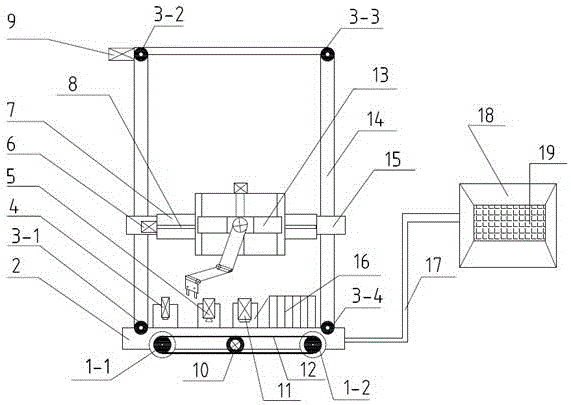
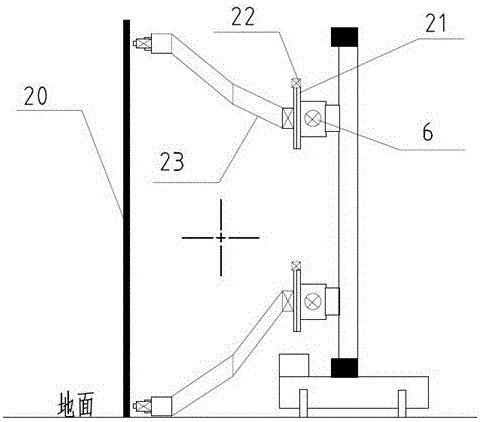
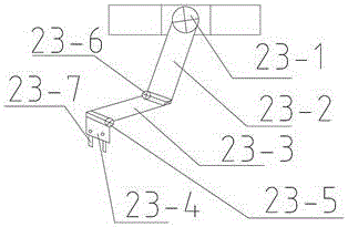
[0061] Turn on the hand-held box controller 18 and set it to manual control mode, perform servo power-on debugging on all motors, and move the chassis 2 to be parallel to the mounting wall through the button on the hand-held box controller 18 and keep it at At a distance of 40-60cm, move the beam slide 15 to a distance of 1 meter from the upper surface of the chassis 2; control the spatial posture of the mechanical arm 23 and the on-off of the biaxial cylinder 23-4, so that the clamp 23-7 is clamped Take out the laser rangefinder 4 and take it out; open the laser rangefinder 4, use the laser rangefinder 4 to measure the data information on the wall surface, and put the laser rangefinder 4 back to the original place after completion; open Man-machine interface 19, input the designed wall tile grid mosaic pattern text information, and according to the measured mounting wall data information, select small tiles with a si...

Embodiment 2

[0062] Example 2: Mounting of bird mosaic patterns on wall tiles

[0063]Turn on the hand-held box controller 18 and set it to manual control mode, perform servo power-on debugging on all motors, and move the chassis 2 to be parallel to the mounting wall through the button on the hand-held box controller 18 and keep it at At a distance of 40-60cm, move the beam slide 15 to a distance of 1 meter from the upper surface of the chassis 2; control the spatial posture of the mechanical arm 23 and the on-off of the biaxial cylinder 23-4, so that the clamp 23-7 is clamped Take out the laser rangefinder 4 and take it out; open the laser rangefinder 4, use the laser rangefinder 4 to measure the data information on the wall surface, and put the laser rangefinder 4 back to the original place after completion; open Man-machine interface 19, input the text information of the designed wall tile bird mosaic pattern, and according to the measured wall surface data information, select the size ...


PUM


Abstract

The invention discloses a method and device of automatically paving wall body mosaic pattern by utilizing small tiles. The device comprises a moving roller, a base plate, a laser distance measuring positioning indicator, an eccentric vibration pneumatic sucking disc, an X-axis motion platform, a large power stepping motor, a cement slurry sprayer, a tooth form synchronous belt, an upright, a beam slide table, a tile sorting feeder, a hand-hold box controller, a human-computer interface, a Z-axis motion platform, a mechanical arm, a double-shaft air cylinder and a clamp; a mechanical arm base is installed on the Z-axis motion platform, the mechanical arm is installed on the mechanical arm base, and the clamp is installed on the double-shaft air cylinder; the laser distance measuring positioning indicator, the eccentric vibration pneumatic sucking disc, the tile sorting feeder and the cement slurry sprayer are stored on the base plate side by side, and option keys of a manual control mode and a procedure control mode are installed on the hand-hold box controller. Compared with traditional manual tile paving, the method and device of automatically paving the wall body mosaic pattern by utilizing the small tiles has the effects that paving efficiency is high, the labor intensity is reduced, and labor cost is remarkably reduced.

Description

technical field [0001] The invention relates to the technical field of architectural decoration, in particular to a method and a device for automatically attaching wall mosaic patterns by using small tiles. Background technique [0002] With the rapid development of the real estate industry in the past 30 years, my country's architectural decoration industry started in the mid-1990s, and is still developing and growing at an annual rate of about 15%. In the traditional building decoration industry, a large number of public buildings, commercial housing and commercial buildings are decorated by hand, especially the installation of wall tiles, which requires skilled workers with technical experience. In recent years, with the advent of the Internet + era, the country has vigorously advocated the development of science and technology, and put forward new requirements for the traditional building decoration industry. On the one hand, the labor cost of skilled workers has increa...

Claims


Application Information

Patent Timeline
IPC IPC(8): E04F21/18B44C3/12
CPCB44C3/126E04F21/1872
Inventor 晁艳普白政民岑辉刘国红赵乐斌
Owner XUCHANG UNIV
Why Eureka
Try Eureka