Well Logging Method for Storing Correlation Flows

A technology related to flow and well logging, which is applied in the direction of construction, etc., can solve the problems of logging accuracy, low water injection, and easy to be affected by formation, so as to improve measurement accuracy, improve measurement accuracy, and eliminate data errors.

Active Publication Date: 2018-02-06
ZHENGZHOU QINGLIN HAOSHENG PETROLEUM TECH DEV CO LTD
View PDF5 Cites 0 Cited by
  • Summary
  • Abstract
  • Description
  • Claims
  • Application Information

AI Technical Summary

Problems solved by technology

[0002] At present, when measuring the flow rate of high-pressure (above 20MP) water injection wells, because the cables cannot be sealed well during the logging process, when the pressure of the water injection well is too high, the injected water may flow out of the overflow pipe at the wellhead, seriously It will overflow from the blowout preventer from time to time, which has a great impact on the environment. Today, as the environment is getting more and more important, this is absolutely not allowed. The traditional solution can only be to collect the liquid in the overflow pipe. There is no good solution for the liquid flowing out of the injector; due to the existence of overflow, it will seriously affect the accuracy of logging calculation results during well logging; usually, the higher the pressure, the more serious the overflow, which is harmful to logging The greater the impact on accuracy, even when the water injection volume is relatively low, all the injected water overflows from the overflow pipe, causing the illusion that the well has not injected water (usually, the higher the pressure, the more difficult the water injection, and the lower the water injection volume )
[0003] For high-pressure wells, the common test method is wireline tracer logging. The principle of tracer logging is to release small solid particle tracers on the upper part of the target layer; in the case of water injection, tracer particles will accumulate in the water-absorbing On the layer, calculate according to the ratio to get the water absorption ratio of each formation, but due to the influence of oil, casing wall and formation porosity, the tracer may also accumulate in the well section without water absorption, or the tracer enters the formation for comparison Depth leads to low measured values
Although this method can solve the problem of wellhead overflow, the measurement accuracy cannot be guaranteed, and it is easily affected by the formation

Method used


Image

  • Well Logging Method for Storing Correlation Flows
  • Well Logging Method for Storing Correlation Flows
  • Well Logging Method for Storing Correlation Flows

Examples


Embodiment 1

[0037] Well: 1

[0038] The basic data of the well condition of a high-pressure and low-injection water injection well in North China are as follows:

[0039] Perforated section: 2940.3-3208.6m; total effective thickness: 36.4m / 11 layers; casing size and depth: 139.7mm×2061.63m; artificial well bottom: 3220.3m; oil pressure: 28.4MPa, water injection pump pressure 29MPa, Daily injection volume: 10m 3 / sky.

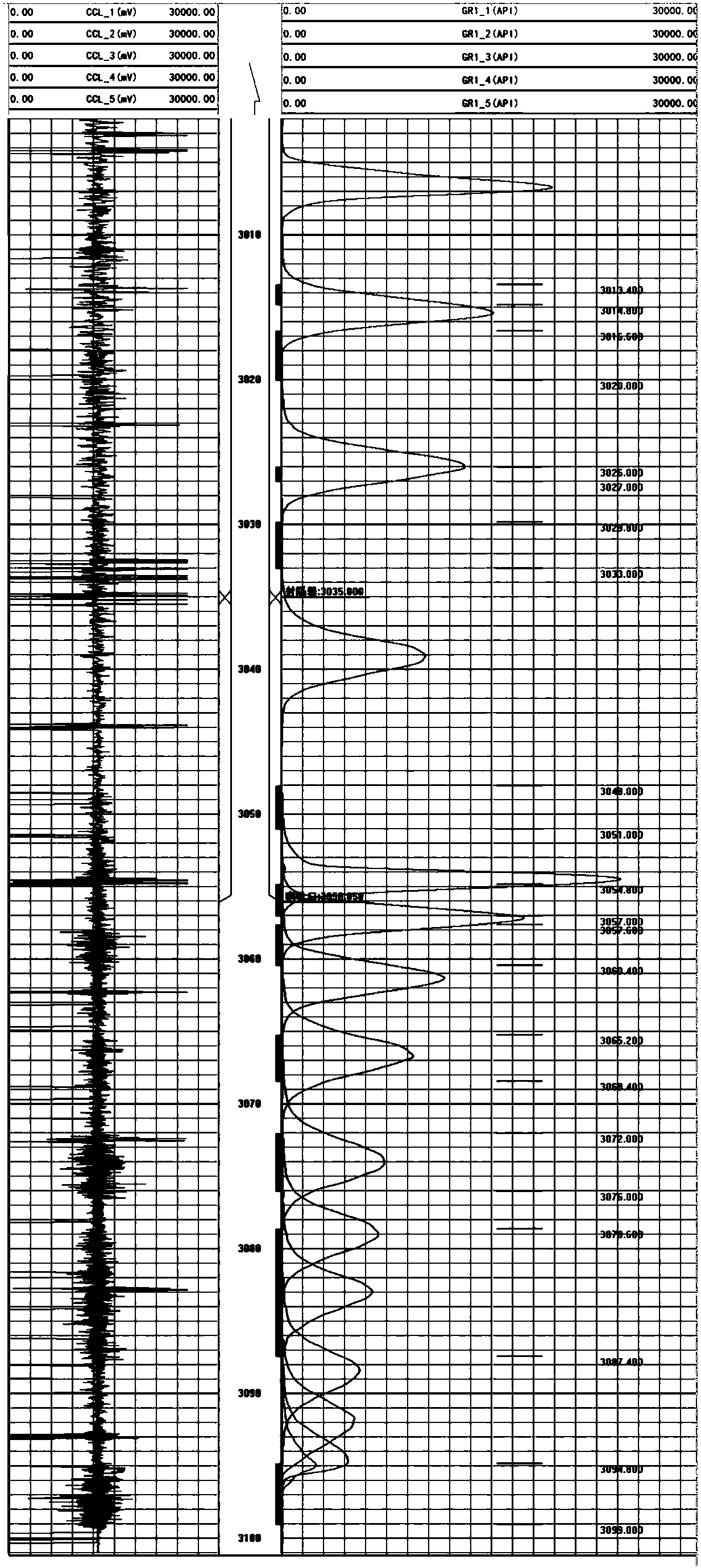
[0040] The specific method of using steel wire logging is as follows:

[0041] Step (1): According to the basic data of the well to be measured (total effective thickness, casing size and depth, ball seat size and depth, artificial bottom hole depth, daily injection rate), the depth of the construction well section and the depth of the perforated well section are set The three parameters measure the working time of the meter and the release start time of the releaser, and synchronize the clock on the meter with the clock on the computer, the tracer strength stored in the...

Embodiment 2

[0049] Well 2: The oil pressure of this well is 11.5MPa, and the water injection flow rate is 50 cubic meters per day. isolation, so that water injection can be finely controlled for each well section);

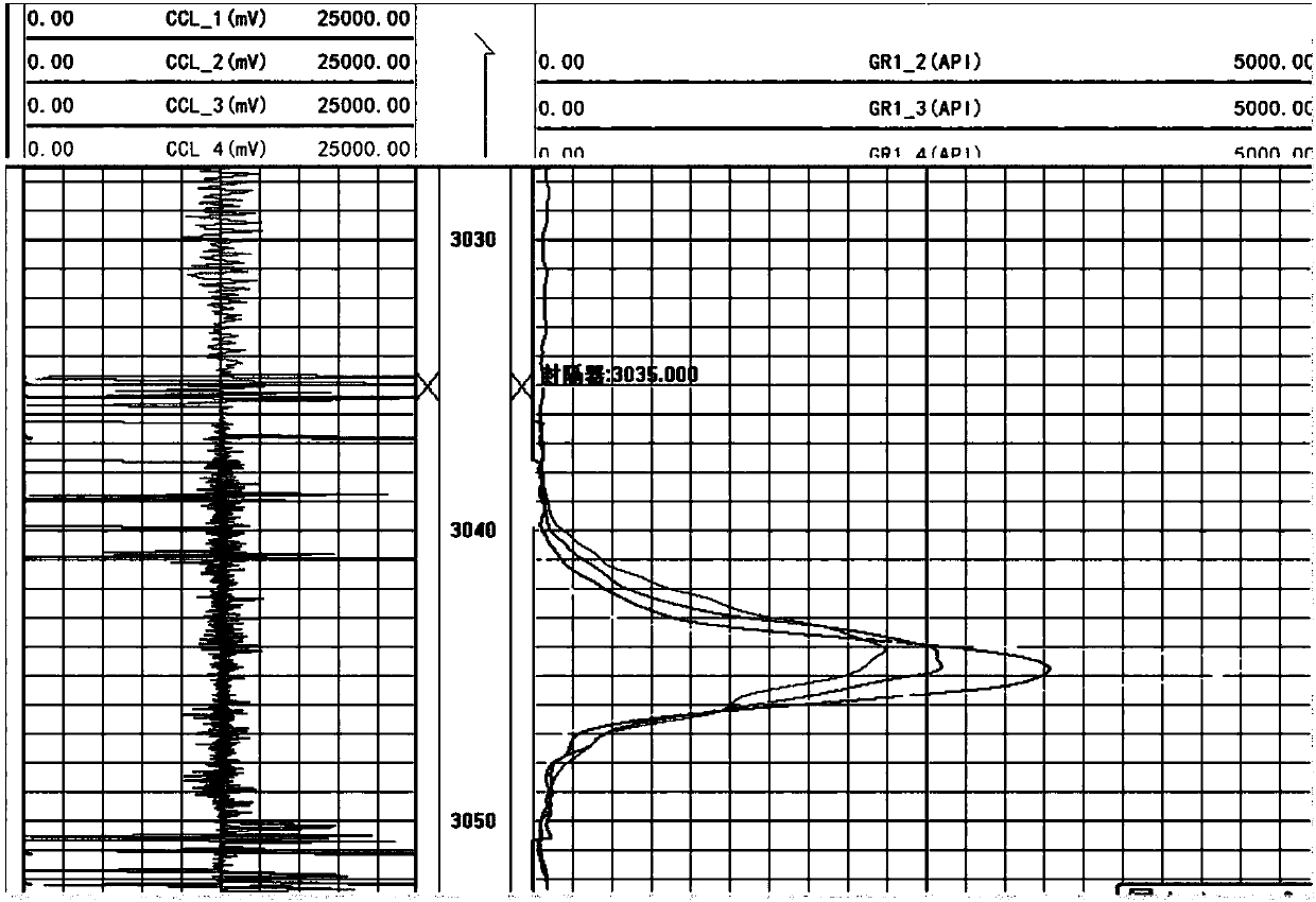
[0050] Steel wire related flow method: The construction steps are as above, after measuring the static temperature (basic curve), then start to measure the related flow three times (one measurement for each faucet, each measurement releases 15 ml of tracer, and a total of 45 ml of tracer is released for three times) After each release of the tracer, the flow meter is lifted up and down to measure the relevant flow rate, and the total measurement is three times).

[0051] After the measurement, the three sets of related data were merged, and the water absorption of the third faucet at the bottom (the main water absorption part of the well) was analyzed this time.

[0052] The merged curve is shown in 2. There is no leakage during the measurement process of the well, so the ut...


PUM


Abstract

The invention discloses a well logging method capable of storing the relative flow rate. The well logging method comprises the following steps that the working time of an instrument and the releasing time of a tracer agent are set according to existing data of a to-be-logged well; an assembled flow instrument is descended into the well through an anti-spraying unit special for a steel wire; a standard curve is measured according to basic data of the well, after being released, the tracer agent is continuously traced according to the data of the well, and detected curve data are recorded through the flow instrument till the working time is over; the flow instrument is got back to the ground, the data recorded in the instrument are read, and then the data and depth data in a depth recorder are combined through the time, the trend of the depth is judged in the combining process, and a plurality of lifting curves and a plurality of lowering curves are obtained; and datum treatment is conducted, depth-correcting calculation is conducted firstly, and then the flow rate of the current depth can be calculated by calculating the lifting curves. According to the well logging method capable of storing the relative flow rate, overflow can be eliminated, so that the error brought by measuring is zero, and under the conditions of being low in injecting quantity and high in pressure, logging accuracy can be greatly improved.

Description

technical field [0001] The invention relates to a well logging method, in particular to a well logging method for storing related flow. Background technique [0002] At present, when measuring the flow rate of high-pressure (above 20MP) water injection wells, because the cables cannot be sealed well during the logging process, when the pressure of the water injection well is too high, the injected water may flow out of the overflow pipe at the wellhead, seriously It will overflow from the blowout preventer from time to time, which has a great impact on the environment. Today, as the environment is getting more and more important, this is absolutely not allowed. The traditional solution can only be to collect the liquid in the overflow pipe. There is no good solution for the liquid flowing out of the injector; due to the existence of overflow, it will seriously affect the accuracy of logging calculation results during well logging; usually, the higher the pressure, the more s...

Claims


Application Information

Patent Timeline
Patent Type & Authority Patents(China)
IPC IPC(8): E21B47/11
CPCE21B47/11
Inventor 剪柳韩永孟爱龙苏伟侯思雨杨士超那晓东
Owner ZHENGZHOU QINGLIN HAOSHENG PETROLEUM TECH DEV CO LTD
Why Eureka
Try Eureka