Cavitation-erosion-preventing novel double-fuel injector and common-rail fuel system

A fuel injection and dual-fuel technology, applied in fuel injection devices, special fuel injection devices, charging systems, etc., can solve problems such as injector failure, noise, wall cavitation, etc., to improve reliability and optimize nozzle structure. , Solve the effect of cavitation

Inactive Publication Date: 2017-05-31
JIANGSU UNIV
View PDF6 Cites 16 Cited by
  • Summary
  • Abstract
  • Description
  • Claims
  • Application Information

AI Technical Summary

Problems solved by technology

However, under the fuel injection pressure as high as 200MPa, or even 300MPa, the strong transient nature of the fuel injection along with the needle valve movement and the existence of multiple injections make the cavitation process have strong unsteady characteristics, and the cavitation bubbles are broken during the instantaneous process. , due to the action of "micro-jet" and "shock wave", the metal wall will be subjected to repeated impacts, which will cause wall cavitation
This kind of cavitation wear will not only worsen the atomization of fuel, and cause the engine to work poorly; moreover, when the cavitation damage is serious, the injector will not even work and will fail directly
[0005] The cavitation of the injector, especially the cavitation caused by the nozzle, causes many hazards. For example, due to the peeling of the cavitation layer, metal debris is mixed into the lubricating oil, which poses a threat to the bearing, resulting in the inability of the injector to work and directly failing, affecting the The injector itself is stiff, causing loud noise and vibration

Method used


Image

  • Cavitation-erosion-preventing novel double-fuel injector and common-rail fuel system
  • Cavitation-erosion-preventing novel double-fuel injector and common-rail fuel system
  • Cavitation-erosion-preventing novel double-fuel injector and common-rail fuel system

Examples


Embodiment Construction

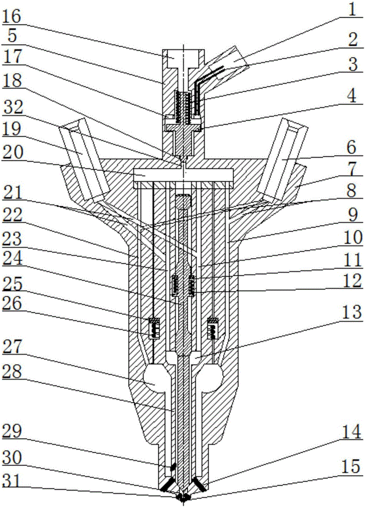
[0033] The present invention will be further described below in conjunction with the accompanying drawings and specific embodiments, but the protection scope of the present invention is not limited thereto.

[0034] Such as figure 1 As shown, the novel anti-cavitation dual-fuel injector of the present invention includes an injector body 7 and an electromagnetic control device 5, and the injector body 7 includes a needle valve 24 arranged in the axial piston cavity of the injector body 7, The second return spring 12 sleeved on the needle valve 24 , the first fuel guide 6 and the second fuel guide 19 arranged at both ends of the tail of the injector body 7 . The needle valve 24 and the injector body 7 form a pair, the upper and lower ends of the second return spring 12 are respectively close to the protruding end of the needle valve 24 and the injector body 7, and the middle and lower parts of the needle valve 24 A second high-pressure fuel chamber 13 is provided on the outer s...


PUM


Abstract

The invention provides a cavitation-erosion-preventing novel double-fuel injector and a common-rail fuel system. The cavitation-erosion-preventing novel double-fuel injector comprises an injector body and an electromagnetic control device. The injector body comprises a needle valve arranged in an injector body axis piston cavity, a second reset spring arranged on the needle valve in a sleeving manner, a first fuel guiding device and a second fuel guiding device, wherein the first fuel guiding device and the second fuel guiding device are arranged at the two ends of the tail of the injector body. The electromagnetic control device is assembled at the tail of the injector body. A cable, a first reset spring, an armature and an electromagnetic valve are arranged in the electromagnetic control device. A common rail fuel system is connected with the two fuel guiding devices of the injector through two fuel high-pressure common-rail pipes to send fuel to the injector. The cavitation-erosion-preventing novel double-fuel injector and the common-rail fuel system are used for achieving in-cylinder direct injection of two different kinds of fuel, and the problem about in-cylinder direct injection of a diesel induced ignition natural gas engine is solved; and the nozzle structure is optimized, and the problem of insufficient lubrication existing in the gas fuel injection process is effectively solved through lubricating injection holes.

Description

technical field [0001] The invention relates to a fuel injector, in particular to a novel anti-cavitation dual-fuel injector and a common rail fuel system, belonging to the technical field of common rail fuel injection systems for diesel engines. Background technique [0002] Internal combustion engines for heavy-duty and industrial applications are typically fueled with diesel, however, there is increasing interest in using gaseous fuels such as natural gas, methane or propane instead of diesel as fuel. Gaseous fuels such as natural gas, methane, or propane are relatively plentiful and relatively inexpensive, and can provide similar levels of power as diesel while producing lower particulate and nitrogen oxide (NO x )emission. However, because gaseous fuels such as natural gas have a higher auto-ignition temperature than diesel, it is necessary to initiate combustion with a pilot injection of diesel fuel prior to introducing natural gas into the combustion chamber. [000...

Claims


Application Information

Patent Timeline
Patent Type & Authority Applications(China)
IPC IPC(8): F02M43/04F02M61/10F02M61/16F02M61/18F02M55/02F02M43/00
CPCF02M43/04F02M43/00F02M55/025F02M61/10F02M61/16F02M61/1806F02M61/1886F02M2200/04
Inventor 张鑫何志霞王谦张文权
Owner JIANGSU UNIV
Why Eureka
Try Eureka