A high-seal centrifugal sand pump and its working method for reducing water erosion

A technology of high sealing and sand pumps, which is applied to pumps for special fluids, parts of pumping devices for elastic fluids, pumps, etc., and can solve problems affecting the service life of equipment, equipment damage and destruction, and wear of centrifugal sand pumps , to achieve high practical life, reduce water erosion, and solve the effect of cavitation problems

Active Publication Date: 2021-04-20
新沂市利源机械有限公司
View PDF5 Cites 0 Cited by
  • Summary
  • Abstract
  • Description
  • Claims
  • Application Information

AI Technical Summary

Problems solved by technology

[0005] 1. The current centrifugal sand pump is prone to wear and tear. Since the sand pump uses centrifugal force to work, the fluid has a large pressure on the inner wall of the equipment, which is prone to wear and cracks, causing damage and destruction of the equipment and affecting the service life of the equipment.
[0006] 2. The pressure near the feeding pipe of the current centrifugal sand pump is low, and cavitation is easy to occur. The cavitation will rupture during the pressurization process, which is easy to cause damage and damage to the equipment and affect the service life of the equipment.

Method used


Image

  • A high-seal centrifugal sand pump and its working method for reducing water erosion
  • A high-seal centrifugal sand pump and its working method for reducing water erosion
  • A high-seal centrifugal sand pump and its working method for reducing water erosion

Examples


Embodiment 1

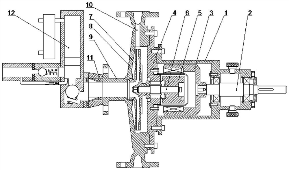
[0031] like Figure 1-5 The high-seal centrifugal sand pump shown to reduce water erosion includes: pump casing 1, motor shaft 2, outer magnetic rotor 3, spacer sleeve 4, inner magnetic rotor 5, transmission shaft 6, impeller 7, end cover 8, inlet The material port 9, the material outlet 10 and the slow flow mechanism 11, the pump casing 1 is pierced with a motor shaft 2, and one end of the motor shaft 2 located in the pump casing 1 is fixedly provided with an external magnetic rotor 3, and the external magnetic A spacer 4 is arranged inside the rotor 3, and the spacer 4 is fixedly arranged on the inner surface of the pump casing 1. An inner magnetic rotor 5 is arranged inside the spacer 4, and a transmission shaft 6 is fixedly arranged at one end of the inner magnetic rotor 5. The transmission shaft 6 is arranged on the spacer sleeve 4 through a bearing, and the end of the transmission shaft 6 away from the inner magnetic rotor 5 is fixedly provided with an impeller 7, and th...

Embodiment 2

[0042] like Figure 1-3 The high-seal centrifugal sand pump shown to reduce water erosion includes: pump casing 1, motor shaft 2, outer magnetic rotor 3, spacer sleeve 4, inner magnetic rotor 5, transmission shaft 6, impeller 7, end cover 8, inlet The material port 9, the material outlet 10 and the slow flow mechanism 11, the pump casing 1 is pierced with a motor shaft 2, and one end of the motor shaft 2 located in the pump casing 1 is fixedly provided with an external magnetic rotor 3, and the external magnetic A spacer 4 is arranged inside the rotor 3, and the spacer 4 is fixedly arranged on the inner surface of the pump casing 1. An inner magnetic rotor 5 is arranged inside the spacer 4, and a transmission shaft 6 is fixedly arranged at one end of the inner magnetic rotor 5. The transmission shaft 6 is arranged on the spacer sleeve 4 through a bearing, and the end of the transmission shaft 6 away from the inner magnetic rotor 5 is fixedly provided with an impeller 7, and the ...

Embodiment 3

[0045] like figure 1 and 4 The high-seal centrifugal sand pump shown to reduce water erosion includes: pump casing 1, motor shaft 2, outer magnetic rotor 3, spacer sleeve 4, inner magnetic rotor 5, transmission shaft 6, impeller 7, end cover 8, inlet The material port 9, the material outlet 10 and the slow flow mechanism 11, the pump casing 1 is pierced with a motor shaft 2, and one end of the motor shaft 2 located in the pump casing 1 is fixedly provided with an external magnetic rotor 3, and the external magnetic A spacer 4 is arranged inside the rotor 3, and the spacer 4 is fixedly arranged on the inner surface of the pump casing 1. An inner magnetic rotor 5 is arranged inside the spacer 4, and a transmission shaft 6 is fixedly arranged at one end of the inner magnetic rotor 5. The transmission shaft 6 is arranged on the spacer sleeve 4 through a bearing, and the end of the transmission shaft 6 away from the inner magnetic rotor 5 is fixedly provided with an impeller 7, an...


PUM


Abstract

The invention discloses a high-seal centrifugal sand pump for reducing water erosion, which comprises: a pump casing, a motor shaft, an outer magnetic rotor, an isolation sleeve, an inner magnetic rotor, a transmission shaft, an impeller, an end cover, a material inlet, a material outlet and a buffer. Flow mechanism, the center of the end cover is provided with a feed port, and the side of the end cover is provided with a discharge port; the feed port is provided with a slow flow mechanism, and the slow flow mechanism includes a slow flow shell, a slow flow groove, a slow flow block and a slow flow spring , the circulation casing is fixedly arranged on the feed inlet, and a slow flow groove is arranged in the slow flow casing, and a slow flow spring is fixedly arranged in the slow flow groove, and a slow flow stopper is arranged at one end of the slow flow spring; on the one hand, the inner wall of the equipment is adopted The buffer structure reduces the pressure of the fluid on the equipment, reduces the damage of the equipment, and has a long service life. On the other hand, it increases the pressure near the feeding pipe, solves the problem of cavitation, improves the working quality of the equipment, and the equipment is not easy to damage and has a practical life. high.

Description

technical field [0001] The invention belongs to the field of material transfer equipment, in particular to a high-seal centrifugal sand pump for reducing water erosion and its working method. Background technique [0002] The centrifugal sand pump is mainly used to support the circulating solid control system of the oil field drilling rig, and its function is to provide drilling fluid with a certain displacement and pressure for the desander, desilter, mixer, etc., so as to ensure the efficient operation of these equipment . Since the emergence of centrifugal pumps in the 1930s and 1940s, they have been in continuous development and have been in a state of great demand in the market. Nowadays, there are more than 600 pump manufacturing enterprises in my country, with an annual output value of nearly 20 billion, which is still rising. It can be seen that the centrifugal sand pump is an indispensable equipment in modern industrial production. [0003] However, due to the hu...

Claims


Application Information

Patent Timeline
Patent Type & Authority Patents(China)
IPC IPC(8): F04D29/42F04D7/04F04D13/06
CPCF04D7/045F04D13/06F04D29/426F04D29/4273F04D29/4286F04D29/4293
Inventor 袁珩博
Owner 新沂市利源机械有限公司
Why Eureka
Try Eureka