
Floating airbag of aerial wind driven generator

A technology of wind turbines and airbags, which is applied in the control of wind turbines, the combination of wind turbines and wind motors, etc. It can solve problems such as difficult adjustment and control of stagnant equipment, reduction of power generation efficiency and safety, rapid fall, etc., and achieve space The position is easy to control, the power generation equipment is protected, and the effect of wind speed and direction changes is small

Inactive Publication Date: 2017-05-31
NORTHWESTERN POLYTECHNICAL UNIV
View PDF12 Cites 2 Cited by
  • Summary
  • Abstract
  • Description
  • Claims
  • Application Information

AI Technical Summary

Problems solved by technology

This type of design is difficult to adjust and control the attitude of the equipment in the air
The specific structure of its fixed generator has not been disclosed, and once a helium leak accident occurs, it is prone to rapid fall, and the power generation efficiency and safety are greatly reduced

Method used


Image

  • Floating airbag of aerial wind driven generator
  • Floating airbag of aerial wind driven generator
  • Floating airbag of aerial wind driven generator

Examples


Embodiment Construction

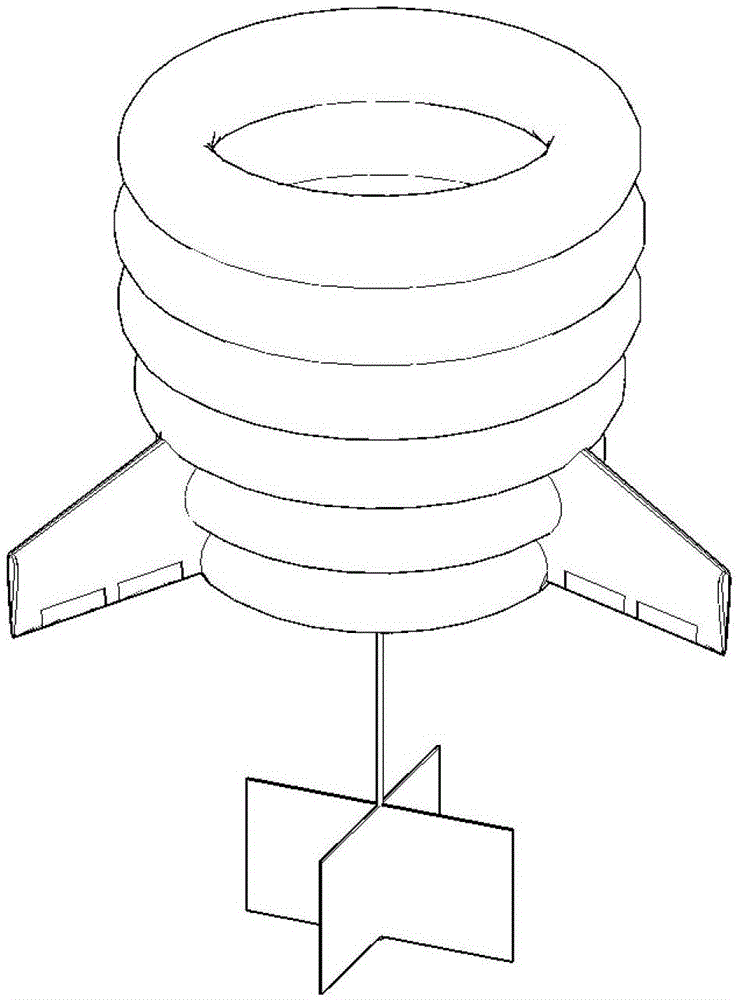
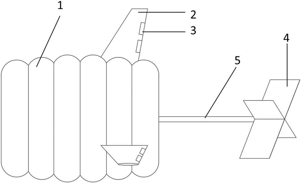
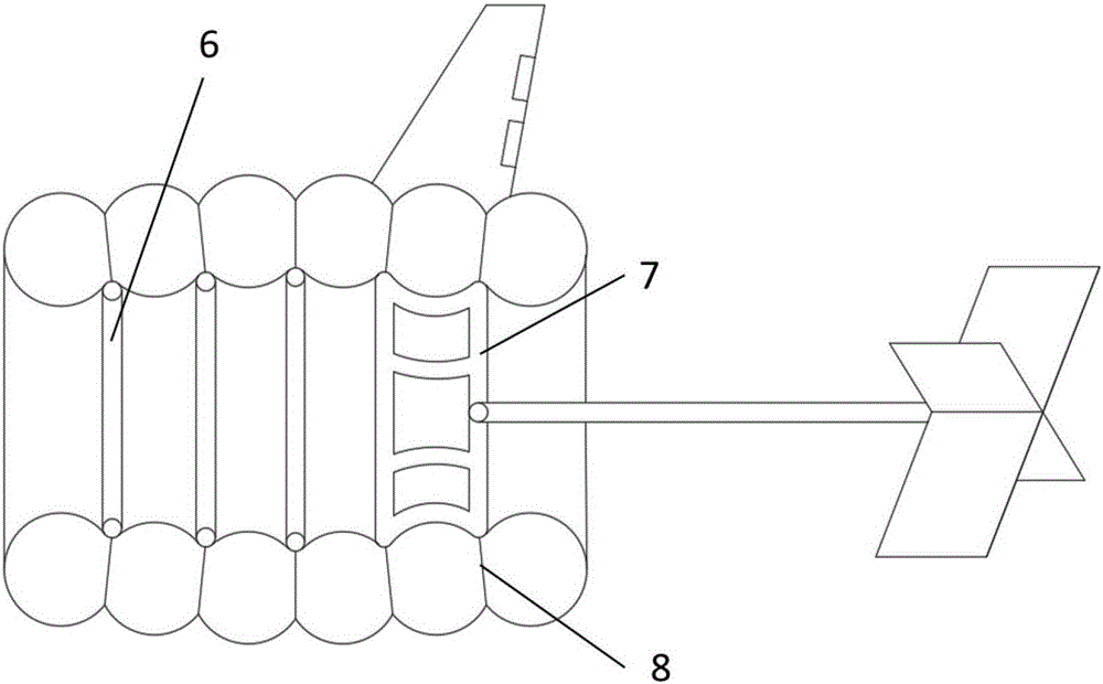
[0023] Six independent ring-shaped helium airbags of different sizes provide full lift, and the independent airbags can effectively reduce the impact caused by airbag damage. The carbon fiber frame structure inside the airbag has two structural forms, one is an independent ring-shaped empty tube structure, and the other is a platform-shaped carbon fiber frame structure, which is used to connect the cross tail rudder plate. The three tail fins are connected to the airbag at intervals of 120°. Each tail fin is equipped with two rudders, which are controlled by stepping motors. With the help of wind force and rudders, the fan is always facing the windward direction. The cross tail rudder plate is connected to the platform-shaped carbon fiber frame inside the airbag by a hydraulic telescopic rod, and undertakes the main direction control task. By controlling the length change of the hydraulic telescopic rod, the front and rear center of gravity of the high-altitude wind turbine ca...


PUM


Abstract

The invention discloses a floating airbag of an aerial wind driven generator. The floating airbag comprises six independent helium airbags, a carbon fiber skeleton, empennages, rudders and a cross tail vane plate. A main body part of the airbag is formed by splicing six independent and annular helium airbags with different sizes, and supplies total lift; and the airbags are independent from each other to effectively prevent sharp fall of the generator caused by damage of the airbags, so that power generation equipment can be protected, the damage of ground facilities can be prevented, and the safety of lower persons is guaranteed. An internal frame structure of the airbag is produced by a carbon fiber synthesis material; and the material is mainly 30 mm-diameter carbon fibers / epoxy resin composite material pipes with different thicknesses. Three empennages are connected to the airbag by 120 degrees at intervals; two rudders are mounted on each empennage, and are controlled to operate by a stepper motor; and a fan is enabled to always align to the windward direction by dint of the wind power and the rudders. The cross tail vane plate is connected to a table-shaped carbon fiber skeleton in the airbag by a hydraulic extension rod, and bears the main direction control task.

Description

technical field [0001] The invention belongs to the technical field of high-altitude wind power generation, and in particular relates to a floating air bag of a high-altitude wind power generator. Background technique [0002] Wind energy is a clean and renewable energy, and the issue of how to efficiently utilize wind energy has drawn attention from all over the world. At present, low-altitude wind power generation technology has matured, and human beings are advancing into the field of high-altitude wind energy. The latest research points out that the density of wind energy increases exponentially with the increase of altitude, and the wind direction and speed are uniform, which is an ideal choice for wind power generation. The wind direction and speed in the airspace at lower altitudes are greatly affected by terrain factors, and are constantly changing and unstable, which limits the utilization of wind energy. Due to technical limitations, mainstream wind turbines are ...

Claims


Application Information

Patent Timeline
IPC IPC(8): F03D9/25F03D7/00F03D5/00
CPCF03D5/00F03D7/00F05B2240/922Y02E10/70
Inventor 吴艳辉赵征汪一舟是介刘汉儒
Owner NORTHWESTERN POLYTECHNICAL UNIV
Learn More