Rubber membrane combined valve element

A combined valve core and rubber diaphragm technology, which is applied in the direction of lift valves, valve devices, engine components, etc., can solve the problems of high risk of seal failure, unstable technical state, and complicated valve core processing technology, so as to improve the service life , to avoid incompatibility between the glue and the medium, and to stabilize the technical state

Active Publication Date: 2017-05-31
XIAN AEROSPACE PROPULSION INST
View PDF6 Cites 0 Cited by
  • Summary
  • Abstract
  • Description
  • Claims
  • Application Information

AI Technical Summary

Problems solved by technology

[0003] In order to solve the problems of complex processing technology, unstable technical state and high risk of sealing failure of the main valve core of the existing pilot valve, the present invention provides a Rubber Diaphragm Combination Spool

Method used


Image

  • Rubber membrane combined valve element
  • Rubber membrane combined valve element
  • Rubber membrane combined valve element

Examples


Embodiment Construction

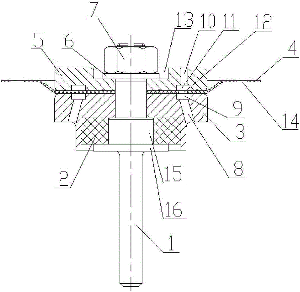
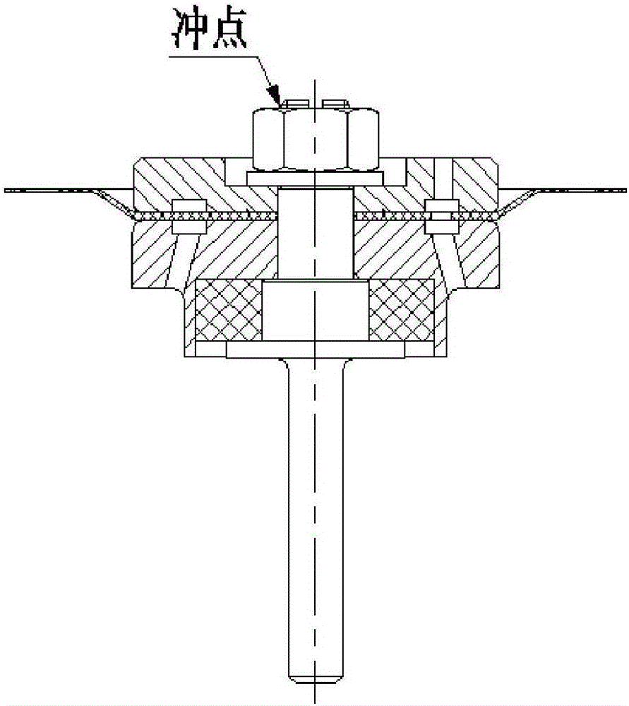
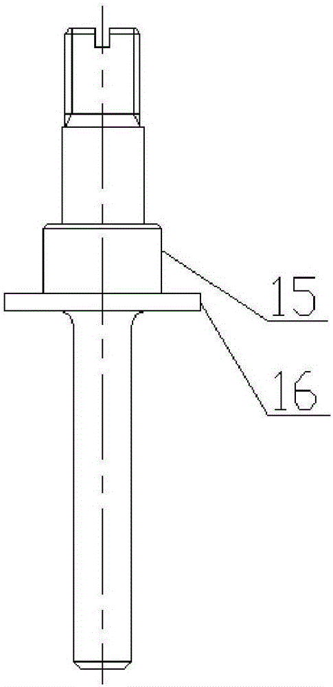
[0032] figure 1 Shown is the rubber diaphragm combination valve core of the present invention, and its assembly sequence is: rubber block 2, valve core 3, diaphragm 4, pressure ring 5 and spring washer 6 are installed on the valve stem 1 in sequence, and finally the nut 7 Press and fasten. Wherein, the rubber block 2 is installed outside the first limiting boss 15 in the middle of the valve stem 1, and is located in the valve core 3, and the compression deformation of the rubber block 2 is controlled by the first limiting boss 15 in the middle of the valve stem 1, The rubber block 2 is connected with the valve core 3 to form a valve core assembly. The lower end of the rubber block 2 is limited by the second limiting boss 16 to prevent it from falling off from the valve core 3 .

[0033] The diaphragm 4 of the present invention adopts a double-layer rubber cloth structure, has high strength and toughness, and has the advantages of large deformation, and the diaphragm 4 has a ...


PUM


Abstract

The invention provides a rubber membrane combined valve element to solve the problem that according to an existing rubber membrane combined valve element, a sealing rubber block comes out under the high-pressure working condition and lower the risk of valve sealing failure. The rubber membrane combined valve element comprises a valve rod, a valve element body, a rubber block, a membrane and a pressing ring. The valve rod is sleeved with the valve element body. A first limiting boss and a second limiting boss are arranged in the middle of the valve rod. The rubber block, the valve element body, the membrane and the pressing ring are sequentially installed on the valve rod and pressed by nuts. The rubber block is located between the valve element and the first limiting boss. The lower end of the rubber block abuts against the second limiting boss. A plurality of pressure leading holes are formed in the end face of the valve element. The end, close to the membrane, of the valve element is provided with an annular convergence groove used for communicating all the pressure leading holes. A pressure relief hole is formed in the end face of the pressing ring. The end, close to the membrane, of the pressing ring is provided with an annular convergence cavity. The annular convergence groove corresponds to the annular convergence cavity in position. A plurality of communicating holes are formed in the end face of the membrane. The communicating holes are located between the convergence groove and the convergence cavity.

Description

technical field [0001] The invention relates to a valve core used for a main valve of a pilot type valve with a large diameter and long service life, in particular to a rubber membrane combined valve core. Background technique [0002] With the increasing requirements for the working pressure of valves in various application fields, the requirements for diameter are also increasing. At home and abroad, when the pressure is high and the diameter is large, the structure of the pilot valve is generally adopted, and the pilot valve is used to drive the main valve, so as to skillfully use the force of the medium to work and achieve large flow. Usually, the main valve core of the pilot valve adopts the rubber vulcanization process to bond with the metal collectively. The problem of incompatibility between liquid and medium increases the risk of valve seal failure. Contents of the invention [0003] In order to solve the problems of complex processing technology, unstable techn...

Claims


Application Information

Patent Timeline
Patent Type & Authority Applications(China)
IPC IPC(8): F16K1/36F16K1/48
CPCF16K1/36F16K1/482F16K1/487
Inventor 徐登伟赵双龙曾维亮孙磊沙超雷小飞李欢
Owner XIAN AEROSPACE PROPULSION INST
Why Eureka
Try Eureka