Coal-derived ethylene glycol steam condensate heat recycling system and method

A coal-to-ethylene glycol and heat recovery technology, which is used in steam generation, preheating, feedwater heaters, etc., can solve problems such as energy waste, reduce resistance and energy waste, ensure smooth transportation, and increase temperature.

Pending Publication Date: 2017-05-31
安阳永金化工有限公司
View PDF4 Cites 5 Cited by
  • Summary
  • Abstract
  • Description
  • Claims
  • Application Information

AI Technical Summary

Problems solved by technology

[0005] The purpose of the present invention is to overcome the shortcomings of the large waste of energy in the above-mentioned prior art and provide a coal-to-ethylene glycol steam condensate heat recovery and utilization system that realizes the cascaded use of steam condensate and fully recovers the waste heat of steam condensate. method

Method used


Image

  • Coal-derived ethylene glycol steam condensate heat recycling system and method
  • Coal-derived ethylene glycol steam condensate heat recycling system and method

Examples


Embodiment 1

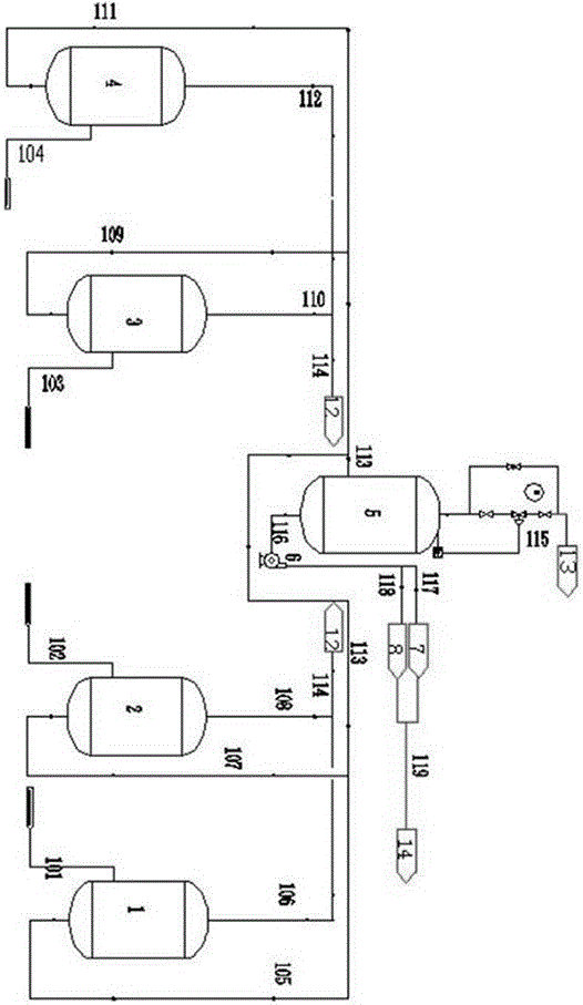
[0019] A coal-to-ethylene glycol steam condensate heat recovery system, such as figure 1 Shown, comprise high grade flash evaporation unit and low pressure flash tank 5, high grade flash evaporation unit comprises first flash evaporation unit, second flash evaporation unit, the 3rd flash evaporation unit and the 4th flash evaporation unit, the first flash evaporation unit The unit includes a first pipeline 101 leading to 0.8MPa condensate, a first flash tank 1 connected to the first pipeline at the inlet end, and a fifth pipeline 105 and the first flash tank provided at the outlet end of the first flash tank condensate The sixth pipeline 106 provided at the outlet end of the gas phase; the second flash unit includes a second pipeline 102 leading to the condensate of the rectification system at 1.5 MPa, a second flash tank 2 connected to the second pipeline at the inlet, and a second flash tank The seventh pipeline 107 arranged at the outlet end of the tank condensate and the e...

Embodiment 2

[0024] A method for recovering heat from coal-to-ethylene glycol steam condensate utilizes the coal-to-ethylene glycol steam condensate heat recovery system in Embodiment 1, and the recovery and utilization system will not be repeated here.

[0025] The recovery method is as follows: the high-grade steam condensate in the coal-to-ethylene glycol process production system enters the high-grade flash unit for flash evaporation, and the high-grade condensate: 1.0MPa steam passes through the heater to exchange heat with the material to form 0.8MPa The condensate enters the first flash tank 1 through the first pipeline 101 for flashing, and the 0.5MPa steam after the flashing is sent into the sixth pipeline 106 through the upper end gas phase outlet of the first flashing tank, and the obtained after flashing The 0.4MPa steam condensate enters the fifth pipeline 105; after the 1.7MPa steam of the rectification system exchanges heat with the material through the heater, the 1.5MPa ste...


PUM


Abstract

The invention relates to the field of coal-derived ethylene glycol, in particular to a coal-derived ethylene glycol steam condensate heat recycling system and method. The coal-derived ethylene glycol steam condensate heat recycling system comprises a high-grade steam flashing unit, a low-grade steam flashing unit and a far heat supply unit taking low-grade steam condensate as heat. The high-grade steam flashing unit inputs steam obtained through flashing of 0.8 MPa condensate, 1.5 MPa condensate of a rectification system, 1.5 MPa condensate of a reaction system and 3.6 MPa condensate in different flashing tanks into a 0.5 MPa steam pipeline net, the obtained 0.4 MPa condensate is subjected to further flashing, 0.2 MPa steam enters a 0.2 MPa steam pipeline net, and the obtained condensate is heated and then fed into a thermoelectric medium pressure steam boiler to serve as supplementary water for the boiler. The coal-derived ethylene glycol steam condensate heat recycling system and method realize cascade use of steam condensate, effective recycling of steam condensate of different regions and different pressure grades is realized through the high-grade flashing unit, pipeline flow resistance and energy waste in the steam condensate collecting process are reduced, and the waste heat of the steam condensate is fully recycled.

Description

technical field [0001] The invention relates to the field of coal-to-ethylene glycol, in particular to a coal-to-ethylene glycol vapor condensate heat recovery system and method. Background technique [0002] In the coal-to-ethylene glycol production process, the various grades of steam required for production are as follows: [0003] [0004] In order to realize the normal operation of the production equipment, after the high-grade steam flashes 0.5MPa steam, the steam condensate is sent to the medium-pressure steam boiler at a pressure of 0.45MPa and a temperature of 155°C as boiler makeup water. The temperature of the condensate is too high, and the steam condensate flashes during the transportation process, which not only causes inaccurate measurement, but also wastes a lot of energy, and the production cost of coal-to-ethylene glycol is greatly increased. Contents of the invention [0005] The purpose of the present invention is to overcome the shortcomings of the...

Claims


Application Information

Patent Timeline
Patent Type & Authority Applications(China)
IPC IPC(8): F22B3/04F22D1/00
CPCF22B3/04F22D1/00
Inventor 张超奇胡贇郜善军王小凯陈帅
Owner 安阳永金化工有限公司
Why Eureka
Try Eureka