Boiler exhaust gas waste heat two-stage recovery and emission reduction device

A waste heat recovery device and boiler flue gas technology, applied in heat recovery systems, heat pumps, heating methods, etc., can solve problems such as poor practicability and complex structure of flue gas waste heat recovery systems, and achieve low consumption, high energy utilization, and high energy efficiency. The effect of low operating costs

Active Publication Date: 2015-12-23
BEIJING ZHICHENGHONGYE INTELLIGENT CONTROL TECH
View PDF8 Cites 0 Cited by
  • Summary
  • Abstract
  • Description
  • Claims
  • Application Information

AI Technical Summary

Problems solved by technology

The flue gas waste heat recovery system is complex in structure and poor in practicability

Method used


Image

  • Boiler exhaust gas waste heat two-stage recovery and emission reduction device

Examples


Embodiment Construction

[0016] The present invention will be further described in detail below in conjunction with the accompanying drawings and specific embodiments.

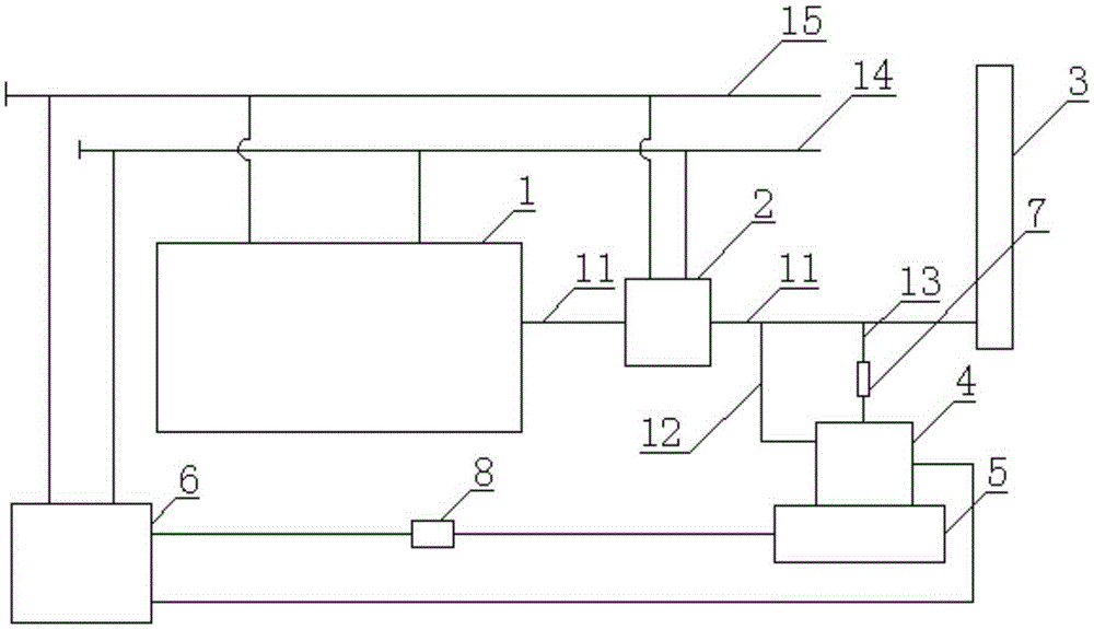
[0017] as attached figure 1 As shown, a boiler flue gas waste heat double-stage recovery and emission reduction device according to the present invention includes a boiler 1 and a burner (not shown in the figure) that supplies heat to the boiler 1, and the boiler 1 is sequentially connected with the waste heat through the main exhaust pipe 11 The recovery device 2 and the chimney 3 are connected; the main exhaust pipe 11 between the waste heat recovery device 2 and the chimney 3 is provided with a branch air intake pipe 12, a branch exhaust pipe 13, and a branch air intake pipe 12, a branch exhaust pipe 13 All are communicated with the mixing tower 4, and the mixing tower 4 is communicated with the water tank 5 through pipelines, and also includes a heat pump 6 communicated with the mixing tower 4 and the water tank 5 respectively, an...


PUM


Abstract

The invention relates to a boiler exhaust gas waste heat two-stage recovery and emission reduction device. The device comprises a boiler and a combustion machine supplying heat to the boiler. The boiler is sequentially communicated with a waste water recovery device and a chimney through a main exhaust pipeline. A branch gas inlet pipeline and a branch exhaust pipeline are arranged on the main exhaust pipeline between the waste heat recovery device and the chimney and communicated with a mixing tower. The mixing tower is communicated with a water tank through a pipeline. The device further comprises a heat pump, a main water inlet pipeline and a main water outlet pipeline, the heat pump is communicated with the mixing tower and the water tank, and the main water inlet pipeline and the main water outlet pipeline are communicated with the heat pump, the boiler and the waste heat recovery device. The boiler exhaust gas waste heat two-stage recovery and emission reduction device has the advantages that the waste heat recovery device and the mixing tower are adopted for waste heat recovery, the temperature of boiler exhaust gas can be reduced to 35 DEG C, waste heat in the exhaust gas is fully recovered, the energy utilization rate is high, the consumption amount is small, operation cost is low, and the energy-saving rate is over 8%.

Description

technical field [0001] The invention relates to the technical field of heating systems, in particular to a two-stage recovery and emission reduction device for boiler flue gas waste heat. Background technique [0002] At present, in the heating industry, some manufacturers install waste heat recovery devices on the flue gas pipelines, and set tube bundles in the waste heat recovery devices, so that the boiler water enters the boiler through the tube bundles in the waste heat recovery devices. When the exhausted flue gas passes through the waste heat recovery devices , will exchange heat with the water in the pipeline, on the one hand, the temperature of the flue gas is reduced, and on the other hand, the temperature of the incoming water is increased. After the boiler is installed with a waste heat recovery device, the exhaust gas temperature at the exhaust outlet can be reduced to about 80 degrees, and the dew point temperature of the flue gas is 58 degrees. Therefore, the ...

Claims


Application Information

Patent Timeline
IPC IPC(8): F24H9/00F25B30/06F24D3/18
CPCY02B30/52Y02P80/15
Inventor 张伟
Owner BEIJING ZHICHENGHONGYE INTELLIGENT CONTROL TECH
Why Eureka
Try Eureka