
Waste heat recycling device for coal-fired kiln

A waste heat recovery and kiln technology, applied in furnaces, waste heat treatment, furnace components, etc., can solve problems such as failure to respond to energy saving, emission reduction, waste of resources, etc.

Inactive Publication Date: 2021-03-16
ANHUI POLYTECHNIC UNIV MECHANICAL & ELECTRICAL COLLEGE
View PDF4 Cites 0 Cited by
  • Summary
  • Abstract
  • Description
  • Claims
  • Application Information

AI Technical Summary

Problems solved by technology

[0004] In view of the above-mentioned technical problems, the purpose of the present invention is to overcome the problems in the prior art that most of the flue gas produced by burning coal is sprayed and desulfurized by lime water through the desulfurization tower, and then discharged, and the flue gas after spraying still has a large amount of Heat, resulting in waste of resources, can not respond to the national call for energy conservation and emission reduction, so as to provide a method that can effectively recover the heat in the flue gas after spraying during use, and can also improve combustion efficiency, so as to Coal-fired kiln waste heat recovery and utilization device that achieves energy saving and emission reduction effects

Method used


Image

  • Waste heat recycling device for coal-fired kiln
  • Waste heat recycling device for coal-fired kiln

Examples


Embodiment Construction

[0030] Specific embodiments of the present invention will be described in detail below in conjunction with the accompanying drawings. It should be understood that the specific embodiments described here are only used to illustrate and explain the present invention, and are not intended to limit the present invention.

[0031] In the present invention, in the absence of a contrary statement, the orientation words included in the term, such as "upper, lower, inner, outer", etc., only represent the orientation of the term in the normal use state, or are understood by those skilled in the art. colloquial term and should not be construed as a limitation of the term.

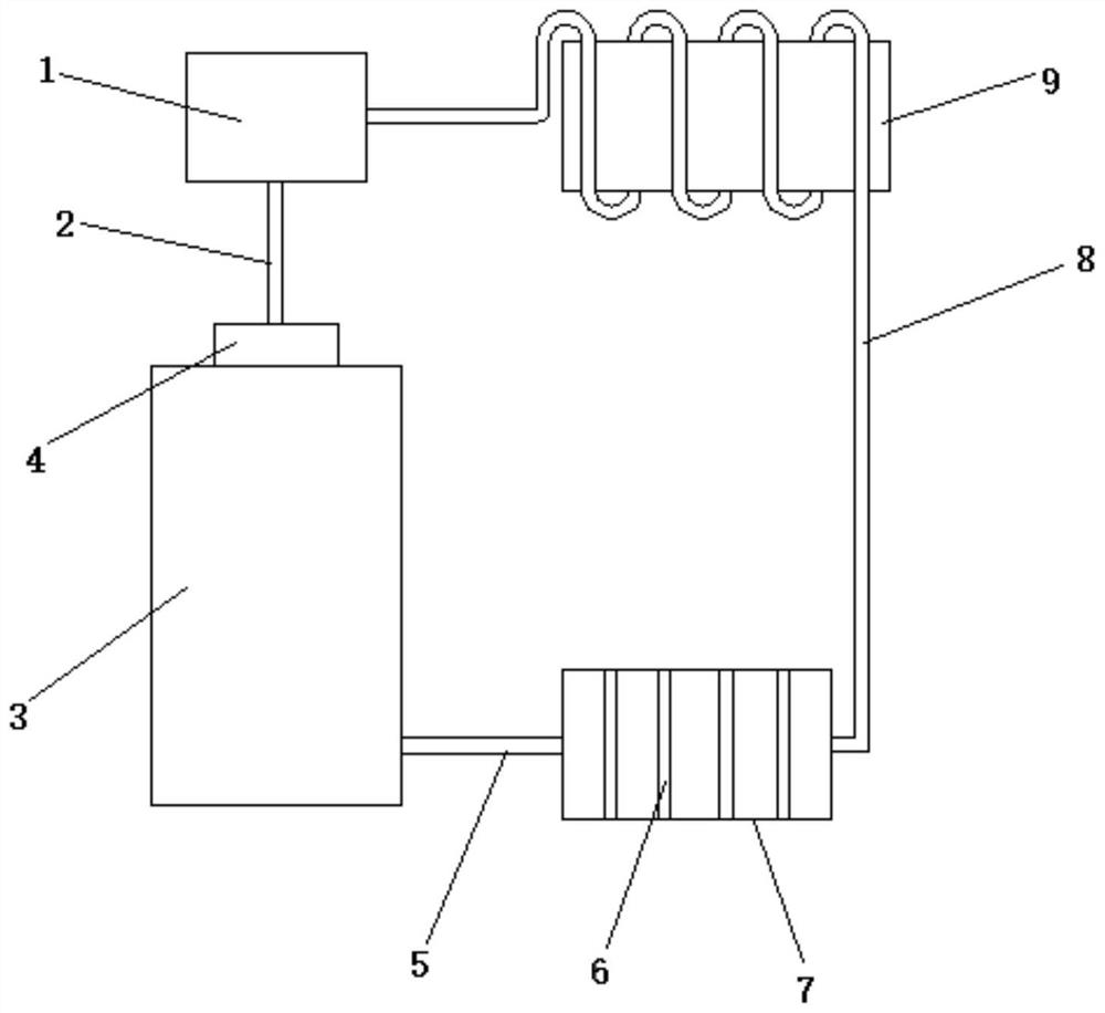
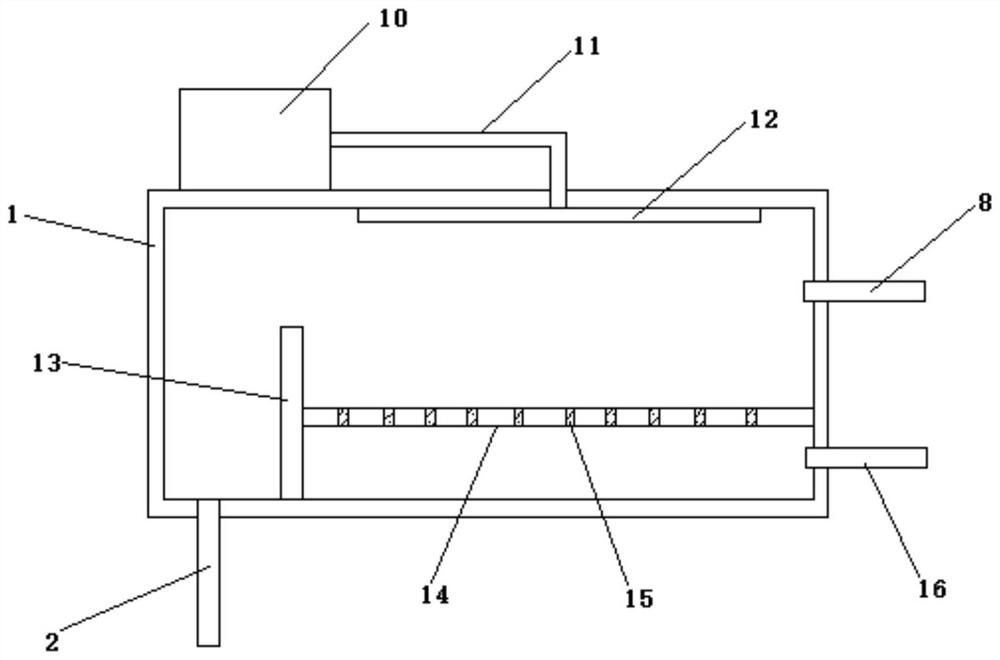
[0032] Such as figure 1 and figure 2 As shown, the present invention provides a waste heat recovery and utilization device for a coal-fired kiln, the device includes: a desulfurization recovery box 1, a raw material preheating box 9 and a heat extraction fan 4;

[0033] The coal-fired kiln 3 is provided with a hot...


PUM


Abstract

The invention discloses a waste heat recycling device for a coal-fired kiln. The waste heat recycling device is characterized by comprising a desulfurization recycling box, a raw material preheating box and a heat extraction fan; the heat extraction fan is arranged on the coal-fired kiln, the heat extraction fan is communicated with the desulfurization recycling box through a second waste heat conveying pipe, the raw material preheating box is arranged between the desulfurization recycling box and the coal-fired kiln, and the raw material preheating box is communicated with the desulfurizationrecycling box and the coal-fired kiln through first waste heat conveying pipes; and an atomizing nozzle is arranged at the top of an inner cavity of the desulfurization recycling box to spray ammoniawater into the inner cavity, a first partition plate is vertically arranged at the bottom of the inner cavity, a second partition plate is horizontally arranged between the first partition plate andone side of the inner cavity, and a plurality of through holes are formed in the second partition plate. According to the waste heat recycling device, the problems that in the prior art, most of fluegas generated by coal combustion is discharged after being subjected to spray desulfurization by lime water through a desulfurization tower, and the sprayed flue gas still has a large amount of heat,so that resource waste is caused, and the national call for energy conservation and emission reduction cannot be responded are solved.

Description

technical field [0001] The invention relates to the technical field of coal-fired kilns, in particular to a waste heat recovery and utilization device for coal-fired kilns. Background technique [0002] Today, with increasingly strict requirements on the atmospheric environment, the awareness of environmental protection has been deeply rooted in people's minds. The flue gas purification and treatment of coal-fired boilers and industrial kilns is very important. The country's energy supply is still dominated by coal. Supplemented by other energy sources, from the perspective of economy and applicability, coal burning is currently the most economical industrial energy source. Others cannot be compared with coal, but coal will inevitably produce sulfur dioxide during the combustion process. If it is discharged randomly, it will pollute the atmosphere. Most of the existing methods are to desulfurize the flue gas produced by coal combustion through the desulfurization tower and s...

Claims


Application Information

Patent Timeline
IPC IPC(8): F27D17/00
CPCF27D17/004F27D17/008Y02P10/25
Inventor 曹春顺
Owner ANHUI POLYTECHNIC UNIV MECHANICAL & ELECTRICAL COLLEGE
Learn More