
Two-stage feed drying device, biomass gasifier and two-stage feed drying method

A drying device and drying method technology, which can be used in biomass drying, drying solid materials, drying gas arrangement, etc., can solve the problem of lack of integrated drying pretreatment equipment and so on.

Active Publication Date: 2021-03-19
SHANGHAI ELECTRICGROUP CORP
View PDF3 Cites 0 Cited by
  • Summary
  • Abstract
  • Description
  • Claims
  • Application Information

AI Technical Summary

Problems solved by technology

[0006] The technical problem to be solved by the present invention is to overcome the technical problem of the lack of an integrated drying pretreatment equipment suitable for biomass gasification system in the prior art, and provide a two-stage feed drying device, biomass gasification furnace and two-stage feed drying method

Method used


Image

  • Two-stage feed drying device, biomass gasifier and two-stage feed drying method
  • Two-stage feed drying device, biomass gasifier and two-stage feed drying method
  • Two-stage feed drying device, biomass gasifier and two-stage feed drying method

Examples


Embodiment 1

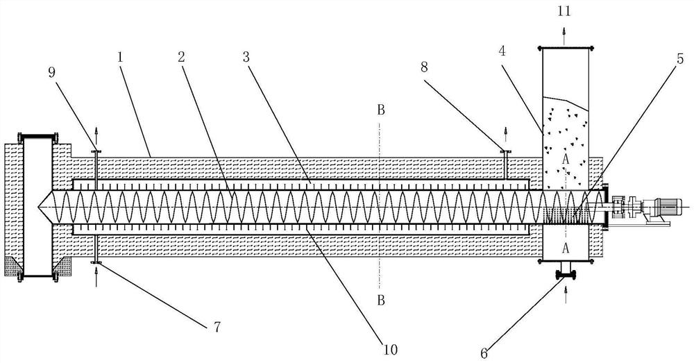
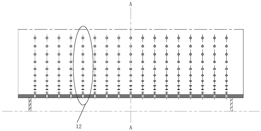
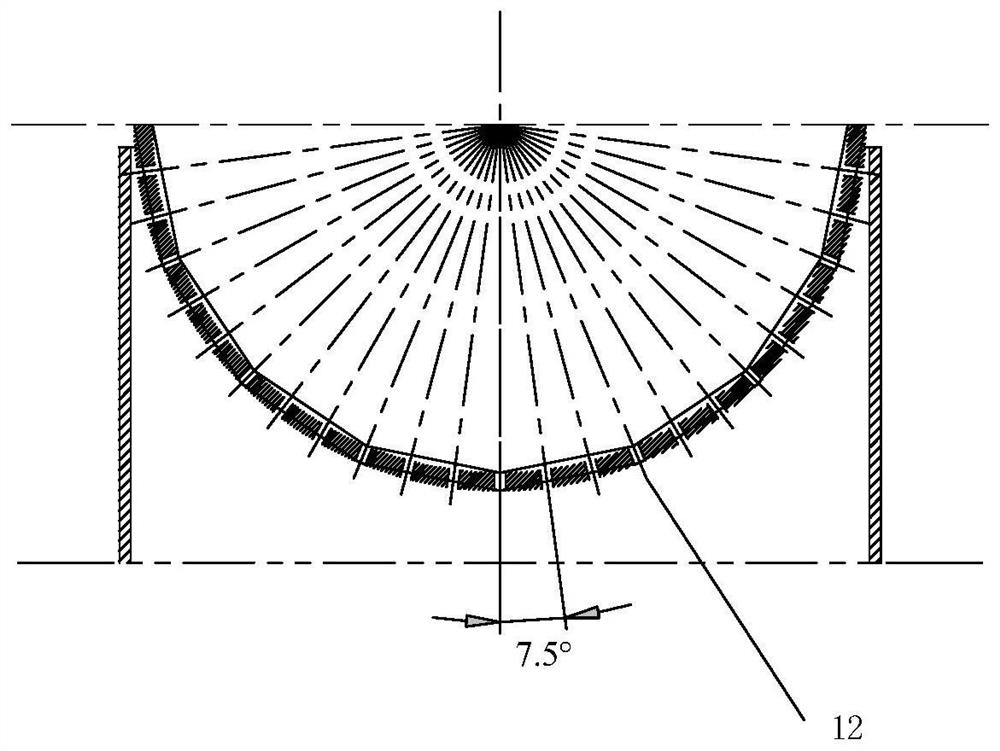
[0037] This embodiment provides a two-stage feed drying device, the specific structure of which is as follows: Figure 1~4 As shown, it includes a drying cylinder 1, a silo 4 and a screw conveyor 2, the silo 4 is arranged at one end of the drying cylinder 1, and the inside of the drying cylinder 1 is also provided with a hollow drying cylinder jacket on the coaxial ring. 3. The inner wall of the drying cylinder jacket 3 forms a hollow material delivery space. The screw conveyor 2 traverses the bottom of the silo 4 and is coaxially welded in the hollow material delivery space. The bottom and top of the silo 4 A first high-temperature flue gas inlet 6 and a first high-temperature flue gas outlet 11 are respectively provided. The lower bottom surface of the drying cylinder 1 away from the end of the silo 4 and the upper top surface of the end close to the silo 4 are respectively provided with a second A high-temperature flue gas inlet 7 and a second high-temperature flue gas outl...

Embodiment 2

[0044] In this embodiment, the structure of the two-stage feed drying device is the same as in Embodiment 1, and the rest of the process parameters and drying effects are shown in Table 1 below.

Embodiment 3

[0046] In this embodiment, the structure of the two-stage feed drying device is the same as in Embodiment 1, and the rest of the process parameters and drying effects are shown in Table 1 below.


PUM


Abstract

The invention discloses a two-stage feeding and drying device, a biomass gasifier, and a two-stage feeding and drying method. The two-stage feeding and drying device comprises a drying cylinder, a feed bin and a spiral conveyer, wherein the feed bin is arranged on one end of the drying cylinder; a drying cylinder jacket with a hollow structure is coaxially and annularly arranged in the drying cylinder; an inner wall surface of the drying cylinder jacket surrounds to form a hollow conveying space; the spiral conveyer transversely penetrates through the bottom part of the feed bin and is coaxially welded into the hollow conveying space; a first high temperature flue gas inlet and a first high temperature flue gas outlet are formed in the bottom part and the top part of the feed bin; a secondhigh temperature flue gas inlet and a second high temperature flue gas outlet are formed in a lower bottom surface of one end, far away from the feed bin, of the drying cylinder, and an upper top surface of one end, close to the feed bin, of the drying cylinder; and the second high temperature flue gas inlet and the second high temperature flue gas outlet penetrate to an outer wall surface of thedrying cylinder jacket from an outer surface of the drying cylinder. The two-stage feeding and drying device and a gasifier are integrally designed, and meanwhile, conveying and drying are realized at the same time, so that the energy consumption is reduced, and the gasification gas quality is improved.

Description

technical field [0001] The invention relates to a two-stage feed drying device, a biomass gasification furnace and a two-stage feed drying method. Background technique [0002] Biomass gasification is a process of partially oxidizing fuel and gasification agent at high temperature to convert biomass fuel into gaseous fuel. Gaseous fuel is easy to transport in pipelines, has high combustion efficiency, is easy to control the combustion process, and has no particulate matter emission, so it is a fuel with high taste. Biomass gasification has high energy conversion efficiency, simple equipment and operation, and is one of the main biomass conversion technologies. [0003] Biomass gasification technology is suitable for solid biomass fuels, including forestry and agricultural waste, processing waste, etc. When biomass raw materials are selected as the input materials of the system, due to the presence of more external moisture in the raw materials, the biomass During the gasif...

Claims


Application Information

Patent Timeline
Patent Type & Authority Patents(China)
IPC IPC(8): F26B3/08F26B17/20F26B21/00F26B25/00C10J3/64
CPCC10J3/64C10J2200/15C10J2300/0909C10J2300/0916F26B3/082F26B17/20F26B21/14F26B25/005F26B2200/02Y02P20/145
Inventor 殷科宛政曾志伟崔洁茹斌聶鑫蕊郭泗勇管志俊
Owner SHANGHAI ELECTRICGROUP CORP
Learn More