
Vacuum pre-cooling machine

A pre-cooler and vacuum technology, which is used in household refrigeration devices, cooling fluid circulation devices, lighting and heating equipment, etc. Avoid the effect of poor cooling effect and secondary pollution

Inactive Publication Date: 2017-05-31
UNIV OF SHANGHAI FOR SCI & TECH
View PDF5 Cites 2 Cited by
  • Summary
  • Abstract
  • Description
  • Claims
  • Application Information

AI Technical Summary

Problems solved by technology

[0004] At present, vacuum pre-coolers on the market mostly use closed water traps. After working for a period of time, a large amount of grease will condense on the surface of the water trap coils. Due to the closed type, it is not conducive to cleaning the coils, resulting in reduced cooling effects and food cooling time. Prolonged, increased production costs
Vacuum cooling technology uses part of the food itself to evaporate and absorb heat to cool down. After vacuum cooling, the food moisture is reduced. Research data shows that the weight loss rate of cooked meat after cooling is 7% to 10%. Too much weight loss will affect the quality and flavor of food. For this reason, the traditional pre-cooler directly uses tap water to replenish water for the product, but this method has uneven water replenishment
After the vacuum pre-cooling is completed, the vacuum chamber needs to be inflated and back-pressurized before the door can be opened to pick up the materials. However, the back-pressure usually adopts direct air or simple filtration. This treatment method has the risk of secondary pollution to food
In addition, although rapid vacuum cooling can inhibit the life activities of some microorganisms, it cannot kill bacteria and cannot fundamentally solve the problem of bacterial reproduction.

Method used


Image

  • Vacuum pre-cooling machine

Examples


Embodiment Construction

[0014] The specific implementation manners of the present invention will be described below in conjunction with the accompanying drawings.

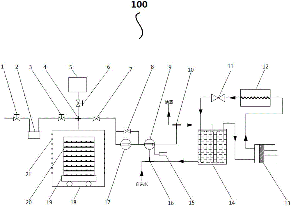
[0015] figure 1 It is a structural schematic diagram of a vacuum precooler of the present invention.

[0016] Such as figure 1 As shown, a vacuum precooler 100 provided by the present invention includes a vacuum system, an ozone generator 2, a refrigeration system and a water supply system.

[0017] The vacuum system has a vacuum chamber 18 , a Roots pump 17 and a water ring pump 9 , the vacuum chamber 18 is used to accommodate materials, and the Roots pump 17 and the water ring pump 9 are used to evacuate the vacuum chamber 18 . The vacuum chamber 18, the Roots pump 17 and the water ring pump 9 are connected in sequence through a vacuum pipeline. In this embodiment, the vacuum system also has a frequency converter 15 connected to the water ring pump 9 for controlling the power of the water ring pump 9 .

[0018] Vacuum chamber 18 int...


PUM


Abstract

The invention provides a vacuum pre-cooling machine which is used for carrying out vacuum pre-cooling on materials. The vacuum pre-cooling machine comprises a vacuum system, an ozone generator, a refrigeration system and a water supplementing system. The vacuum system is provided with a vacuum chamber, a Roots pump and a water ring pump, which are connected in sequence through a vacuum pipeline; the vacuum chamber is used for storing materials; the Roots pump and the water ring pump are used for vacuumizing the vacuum chamber; the ozone generator is communicated with the vacuum chamber through a pipeline and is used for carrying out pressure returning, sterilization and disinfection on the vacuum chamber; the refrigeration system is used for cooling gas pumped by the Roots pump and the water ring pump and is provided with an open type water catching device, a compressor and a condenser, which are connected in sequence through a pipeline; the open type water catching device is further connected with the water ring pump through a pipeline; the water supplementing system is provided with a water tank of small molecule water, which is communicated with the vacuum chamber, and is used for supplementing water for materials; the water tank of the small molecule water is used for storing the small molecule water.

Description

technical field [0001] The invention belongs to the field of cooling equipment, and in particular relates to a vacuum precooler. Background technique [0002] Vacuum cooling means that when the material is put into a closed vacuum box that can withstand a certain negative pressure and is pumped by a suitable vacuum system, as the vacuum degree in the vacuum box continues to increase, the boiling point temperature of the water will continue to decrease, and the water will It becomes easy to vaporize. When water vaporizes, it can only absorb heat from the material itself, so the material can be cooled rapidly. [0003] Vacuum cooling is a fast and clean food cooling technology. It has the advantages of long fresh-keeping time, short cooling time, and no pollution to the environment. It is widely used in cooling vegetables, fruits, seafood, and cooked food. [0004] At present, vacuum pre-coolers on the market mostly use closed water traps. After working for a period of time, ...

Claims


Application Information

Patent Timeline
IPC IPC(8): F25D31/00
CPCF25D31/00F25D2317/043
Inventor 李保国刘山山顾小杰高志新王崇好白旭生仇富强何小梁
Owner UNIV OF SHANGHAI FOR SCI & TECH
Features
  • Generate Ideas
  • Intellectual Property
  • Life Sciences
  • Materials
  • Tech Scout
  • Unparalleled Data Quality
  • Higher Quality Content
  • 60% Fewer Hallucinations
Learn More