Flue-smoke-removal-type smoke condensation waste heat recycling system

A technology of flue gas condensation and waste heat recovery, applied in the field of boilers, can solve the problems of low recovery rate, troublesome operation, and poor temperature controllability of the economizer, and achieve the effects of good effect, reduced labor cost, and good smoke removal effect.

Inactive Publication Date: 2017-05-31
WUXI XIYUAN BOILER
View PDF6 Cites 4 Cited by
  • Summary
  • Abstract
  • Description
  • Claims
  • Application Information

AI Technical Summary

Problems solved by technology

[0002] The gas-fired hot water boiler in the prior art has a low recycling rate, and the economizer has poor controllability to the water temperature, which requires regular adjustment and troublesome operation; the flue gas is directly discharged to the outside, because the flue gas will be mixed with Some dust, directly discharged to affect the environment

Method used


Image

  • Flue-smoke-removal-type smoke condensation waste heat recycling system
  • Flue-smoke-removal-type smoke condensation waste heat recycling system

Examples


Embodiment Construction

[0011] The specific embodiments of the present invention will be further described below in conjunction with the accompanying drawings.

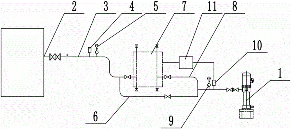
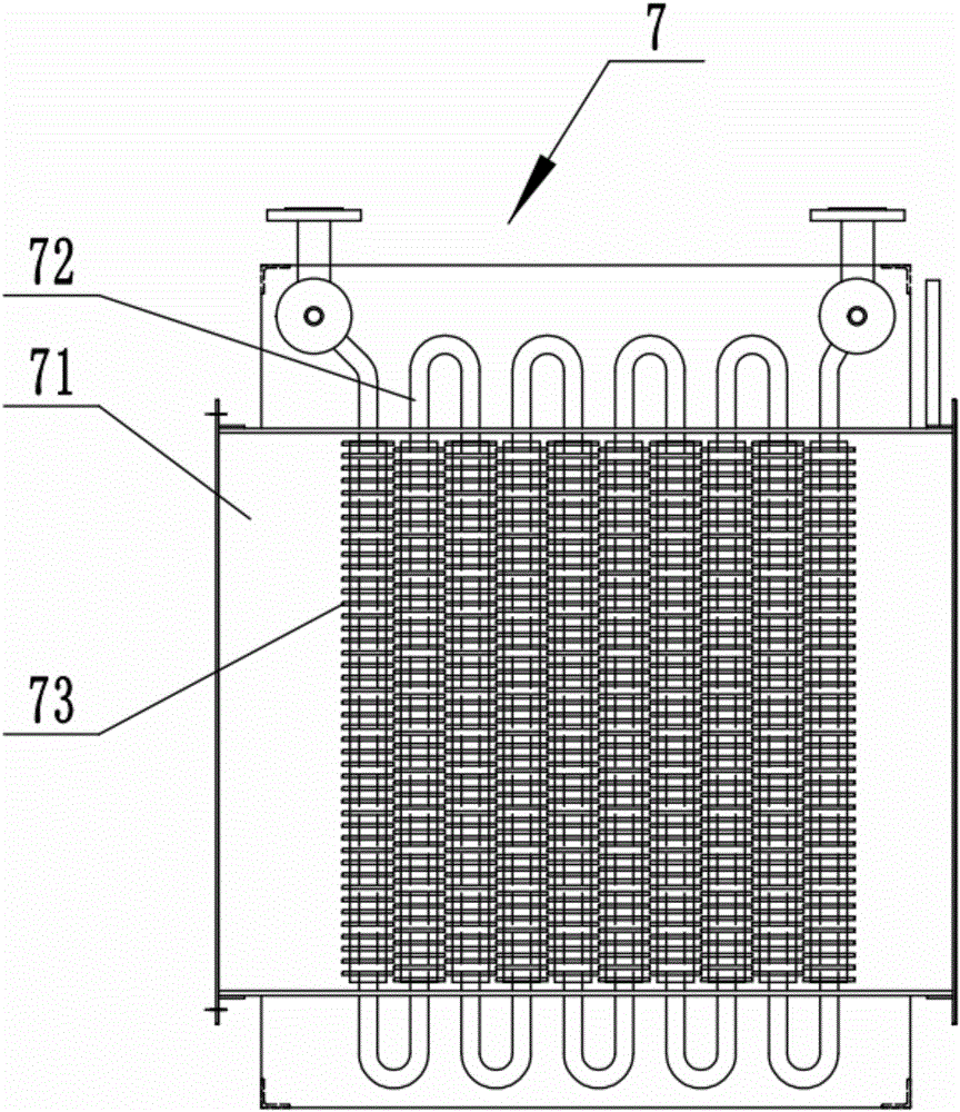
[0012] Such as figure 1 As shown, the flue gas removal flue gas condensation waste heat recovery and utilization system of this embodiment includes a water pump 1, a first pipeline 8 is installed at the water outlet of the water pump 1, and the first pipeline 8 is connected to the inlet of the economizer 7, The outlet of the economizer 7 communicates with the water inlet 2 of the boiler through the third pipeline 3, and the second pipeline 6 is branched from the first pipeline 8, and the second pipeline 6 directly communicates with the third pipeline 3, and the second A switch valve is installed on the pipeline 6; a first thermometer 10 and a first pressure gauge 9 are installed on the first pipeline 8; a second thermometer 4 and a second pressure gauge 5 are installed on the third pipeline 3, and a A controller 11, the input end of the con...


PUM


Abstract

The invention relates to a flue-smoke-removal-type smoke condensation waste heat recycling system. The flue-smoke-removal-type smoke condensation waste heat recycling system comprises a water pump, wherein a first pipeline is installed at a water outlet of a water pump, the first pipeline is connected to an inlet of an energy saver, an outlet of the energy saver is communicated with a water inlet of a boiler by virtue of a third pipeline, the first pipeline is also branched to form a second pipeline, the second pipeline is directly communicated with the third pipeline, and a switch valve is installed on the second pipeline; the first pipeline is provided with a first thermometer and a first pressure gauge; the third pipeline is provided with a second thermometer and a second pressure gauge, and the flue-smoke-removal-type smoke condensation waste heat recycling system also comprises a controller, wherein an input end of the controller is connected with the first thermometer, an output end is connected with the energy saver, and the controller controls the power of the energy saver according to a temperature signal detected by the first thermometer.

Description

technical field [0001] The invention relates to the technical field of boilers, in particular to a boiler waste heat recovery and utilization system. Background technique [0002] The gas-fired hot water boiler in the prior art has a low recycling rate, and the economizer has poor controllability to the water temperature, which requires regular adjustment and troublesome operation; the flue gas is directly discharged to the outside, because the flue gas will be mixed with Some dust, direct discharge affects the environment. Contents of the invention [0003] Aiming at the above-mentioned problems existing in the prior art, the present invention provides a flue gas removal system for recovery and utilization of waste heat from condensation of flue gas. The present invention adopts the following scheme: [0004] A flue gas removal flue gas condensation waste heat recovery system, including a water pump, a first pipeline is installed at the water outlet of the water pump, th...

Claims


Application Information

Patent Timeline
Patent Type & Authority Applications(China)
IPC IPC(8): F28B1/02F28B11/00F28F1/30F23J15/02
CPCF28B1/02F23J15/022F23J2217/20F28B11/00F28F1/30
Inventor 宋大强
Owner WUXI XIYUAN BOILER
Why Eureka
Try Eureka