Explosion switch based on multi-side energy collecting jet flow

An energy-gathering jet and energy-gathering technology, which is applied in the field of electrical switches, can solve the problems of weakening the mechanical properties of the switch and the low utilization rate of explosive energy, and achieves the effects of preventing re-breakdown, improving safety, and reducing usage.

Active Publication Date: 2017-05-31
UNIV OF SCI & TECH OF CHINA
View PDF5 Cites 8 Cited by
  • Summary
  • Abstract
  • Description
  • Claims
  • Application Information

AI Technical Summary

Problems solved by technology

The working principle of the traditional explosive switch is to use the powerful shock wave generated by the explosion of the explosive to drive the cutting body to cut the conductor, so the energy utilization rate of the explosive is not high, and in order to improve the cutting efficiency, it is usually necessary to weaken the conductor, which weakens the mechanical properties of the switch

Method used


Image

  • Explosion switch based on multi-side energy collecting jet flow
  • Explosion switch based on multi-side energy collecting jet flow
  • Explosion switch based on multi-side energy collecting jet flow

Examples


Embodiment 1

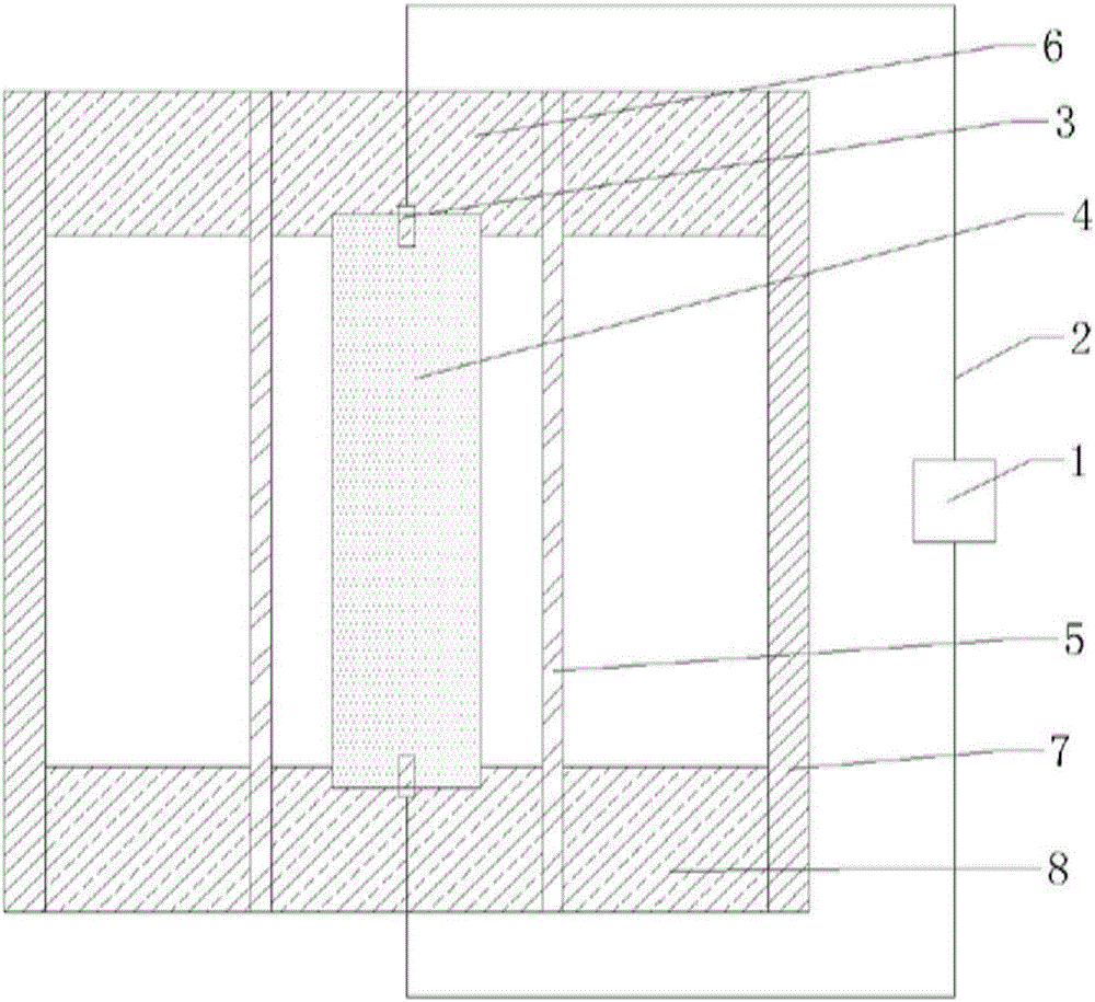
[0025] Such as figure 1 Shown, a kind of explosion switch based on multi-faceted concentrated energy jet, outermost layer is protective cylinder (7), and size is: wall thickness 1cm, height 20cm, internal diameter is 24cm, and material is high-strength epoxy. A protective end cover (8) with a wall thickness of 2cm is provided on its upper and lower sides, and its outer side and the protective cylinder (7) are fixed with bolts, and a through hole with an inner diameter of 8.4cm is opened in the center, and is fitted through an interference fit. Fix with the upper and lower two ends of the conductor (5) respectively. The shape of the conductor (5) is a round tube, the size is: inner diameter 8cm, wall thickness 0.3cm, height 20cm, and the material is red copper. Conductor end caps (6) with a diameter of 8.2 are arranged on the inner side of the conductor (5) at the upper and lower ends, and are connected with the conductor (5) through interference fit. There is a through hole ...

Embodiment 2

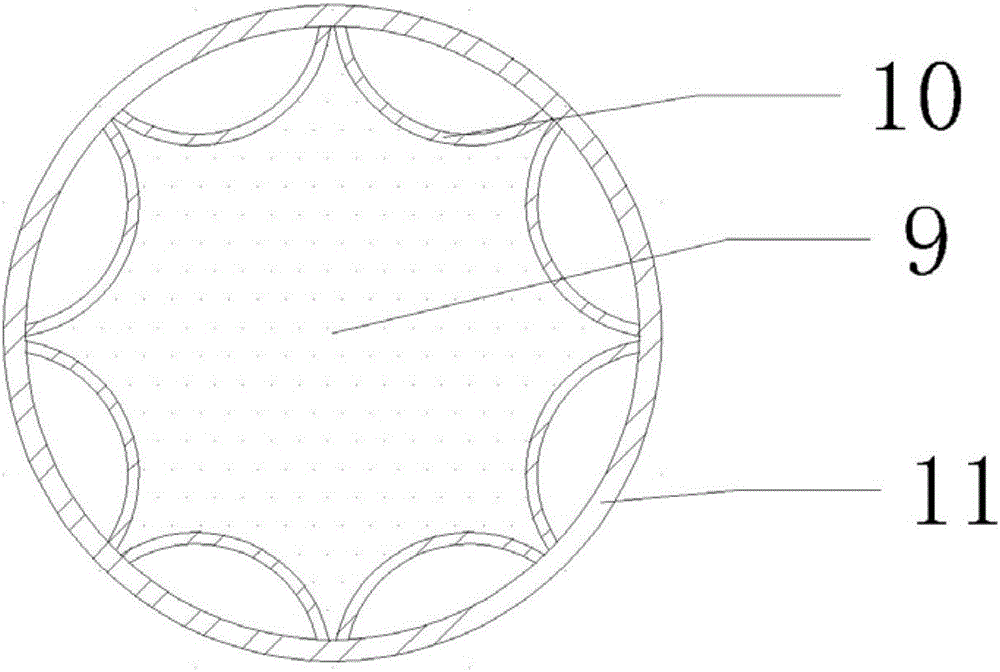
[0027] The difference from Example 1 is that both the annular energy-shaping charge cover and the axial energy-shaping charge cover in the multi-faceted circumferential energy-shaping charge pack adopt tapered drug-form covers in cross-section, wherein the axial shape-forming charge The cover cone angle is 60 degrees, and two adjacent drug-shaped covers are tangent at the inner wall of the shell. The cone angle of the circumferential energy-concentrating drug-shaped cover is also 60 degrees, and the distance between the opening ends is 2 cm.

[0028] The basic working process of the present invention is:

[0029] When the circuit needs to be disconnected, the explosive is detonated from the two ends and spreads to the center. Under the action of strong explosion pressure, the axial shaped charge cover is crushed and 8 "jet knives" are formed along the axial direction, and the conductor There are 8 pieces along the axial direction. When the detonation wave at the two ends reac...


PUM


Abstract

The invention discloses an explosion switch based on multi-side energy collecting jet flow. The switch belongs to a normally-closed one-time switch and comprises an exploder, an access device and a protection device. A conductor is cut through the energy collecting jet flow, the explosive energy utilization rate is increased, the disconnection time is shortened, meanwhile, a method combining the axial energy collecting jet flow and the circumferential energy collecting jet flow is adopted, the two ends of the disconnected conductor are spaced by a long distance, and the danger that the disconnected switch is broken down again under the high voltage condition can be effectively avoided. In addition, the conductor is not subjected to any weakening treatment, so that the conductor is excellent in mechanical performance and can be suitable for various adverse working conditions.

Description

technical field [0001] The invention belongs to the technical field of electric switches, and specifically relates to an explosive switch based on multi-faceted energy-gathering jets. Protection switch for power circuits. Background technique [0002] The explosion has the characteristics of fast work speed and strong work ability. Therefore, compared with the traditional electric switch, the explosive switch with explosives as the driving energy has the advantages of high current resistance, fast circuit breaking speed, low impedance before circuit breaking, and high impedance after circuit breaking. Therefore, explosive switches are widely used in high-power circuits and inductive energy storage systems. Researchers from various countries have successively invented various explosive switches, and some switches have been able to withstand hundreds of kiloamperes of current and can achieve a circuit breaking effect within 100 microseconds. The working principle of the trad...

Claims


Application Information

Patent Timeline
Patent Type & Authority Applications(China)
IPC IPC(8): F42B3/00F42B39/02H01H39/00
CPCF42B3/00F42B39/02H01H39/00
Inventor 马宏昊杨明沈兆武张莉陈艳
Owner UNIV OF SCI & TECH OF CHINA
Why Eureka
Try Eureka