Guide rod device for stage separation of guided missile

A technology of inter-stage separation and guide rod, which is applied to self-propelled projectiles, projectiles, offensive equipment, etc., can solve the problems of upper-stage missile attitude interference, affecting the flight range of missiles, etc., to achieve low production cost, ensure stability, The effect of the overall structure is simple

Active Publication Date: 2017-05-31
BEIHANG UNIV
View PDF5 Cites 1 Cited by
  • Summary
  • Abstract
  • Description
  • Claims
  • Application Information

AI Technical Summary

Problems solved by technology

The separation surface of the traditional inter-stage separation device is generally at the front end of the next-stage missile body, which leads to the fact that after the separation process is completed, the negative mass such as the wall of the transition chamber still follows the flight of the upper-stage missile, which affects the actual flight of the missile. At the same time, the traditional missile inter-stage separation device cannot guarantee the smooth and smooth separation process of the separation process, and the disturbance of the next-stage missile during the separation process will seriously interfere with the attitude of the upper-stage missile. In order to solve the problem of the separation device between the missile stages, a guide rod device for the separation between the missile stages was invented

Method used


Image

  • Guide rod device for stage separation of guided missile
  • Guide rod device for stage separation of guided missile
  • Guide rod device for stage separation of guided missile

Examples


Embodiment Construction

[0031] The present invention will be further described below in conjunction with the accompanying drawings and embodiments.

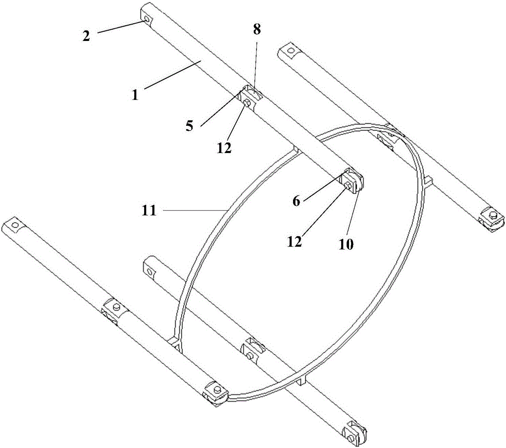
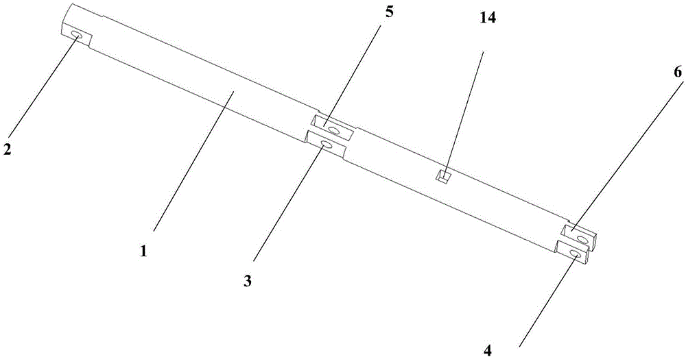
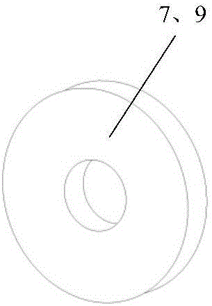
[0032] See figure 1 , figure 2 and Figure 6 , the guide rod device that the present invention separates between a kind of missile stage, it is by cylindrical guide rod 1, the first annular pulley 7, the second annular pulley 9, the first annular rubber ring 8, the second An annular rubber ring 10, a support ring 11, bolts and nuts 12, etc.; the positional connection relationship between them is: the cylindrical guide rod 1 is fixed on the upper stage missile through the first circular through hole 2 and the bolts and nuts 12. Tail 15, four cylindrical guide rods 1 are evenly distributed and fixed on the upper missile tail 15, the first annular rubber ring 8 and the second annular rubber ring 10 can be directly sleeved on the first annular pulley 7 , In the outer end groove of the second annular pulley 9, the first annular pulley 7 is fixed in the f...


PUM


Abstract

The invention discloses a guide rod device for stage separation of a guided missile. The guide rod device comprises cylindrical guide rods, first circular pulleys, second circular pulleys, first circular rubber rings, second circular rubber rings, a supporting ring, bolts, nuts and the like, wherein the cylindrical guide rods are fixed at the tail of a previous-stage guide missile through first circular through holes, the bolts and the nuts; the corresponding circular rubber rings can be directly sleeved with grooves in the outer ends of the circular pulleys; each first circular pulley is fixed in a first rectangular through hole in the middle of the corresponding cylindrical guide rod through a second circular through hole, the bolts and the nuts; each second circular pulley is fixed in a second rectangular through hole in the tail end of the corresponding cylindrical guide rod through a third circular through hole, the bolts and the nuts; the supporting ring is in interference fit and fixation with cuboid grooves in the lower surfaces of the four cylindrical guide rods through cuboid bosses which are uniformly distributed at the periphery. According to the guide rod device disclosed by the invention, the negative mass can be removed, the structure is simple, the stability in the separation process is guaranteed, the separation is enabled to quicker and the production cost is effectively reduced.

Description

[0001] Technical field: [0002] The invention relates to a guide rod device for separation between missile stages, and belongs to the technical field of separation between missile stages. [0003] technical background: [0004] The design of the missile inter-stage separation device has always been very important in the development of missiles. Since high speed and long range have become an important development direction in the field of conventional weapon research, the propellant must be increased to increase the speed and range of the missile. The mass, which in turn leads to an increase in the volume of the missile, and when the fuel is used up, the storage bins used to store the fuel become a negative mass, which affects the flight characteristics of the subsequent stages of the missile. A missile with a multi-stage layout can effectively resolve the above-mentioned conflicts. It can not only make full use of the energy provided by the fuel in the engine, but also throw a...

Claims


Application Information

Patent Timeline
Patent Type & Authority Applications(China)
IPC IPC(8): F42B15/36
CPCF42B15/36
Inventor 王晓慧钱程
Owner BEIHANG UNIV
Why Eureka
Try Eureka