Internet of Things-based landfill leakage monitoring system

A landfill and monitoring system technology, which is applied in the field of landfill leakage monitoring system based on the Internet of Things, can solve the problems of real-time remote control, low detection horizontal resolution, and complicated wiring settings, etc., to achieve the realization of arrangement Effects of monitoring, expanding the scope of monitoring, and ensuring accuracy

Inactive Publication Date: 2017-05-31
武汉地大物探遥感有限公司
6 Cites 6 Cited by

AI-Extracted Technical Summary

Problems solved by technology

This method is time-consuming and laborious, has a certain hysteresis, cannot carry out real-time remote control, and each electrode is independent, and needs t...

Abstract

The invention relates to an Internet of Things-based landfill leakage monitoring system. A landfill includes a waste filling layer, a gravel diversion layer, an on-film clay layer and an under-film clay layer; the bottom of the on-film clay layer, the waste filling layer, the gravel diversion layer and two sides of the on-film clay layer are wrapped with an impermeable film; the lower side of the impermeable film is provided with an automatic resistivity acquisition system; the automatic resistivity acquisition system comprises a cable, a detection sensor and a high density electrical prospecting instrument, wherein the cable is arranged continuously at the lower side of the impermeable film to form a plurality of bow-shaped structures, the detection sensor is arranged on the cable, and the high-density electrical prospecting instrument is fixedly connected at the tail end of the cable; the automatic resistivity acquisition system is connected with a cloud service platform; the cloud service platform is connected with a control terminal; and the control terminal is connected with an automatic data processing system. The Internet of Things-based landfill leakage monitoring system of the invention has the advantages of real-time monitoring, remote operation, comprehensive and accurate monitoring and wide coverage.

Application Domain

Detection of fluid at leakage point

Technology Topic

Internet of ThingsElectricity +9

Image

  • Internet of Things-based landfill leakage monitoring system
  • Internet of Things-based landfill leakage monitoring system
  • Internet of Things-based landfill leakage monitoring system

Examples

  • Experimental program(1)

Example Embodiment

[0019] Example 1
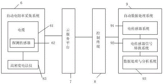
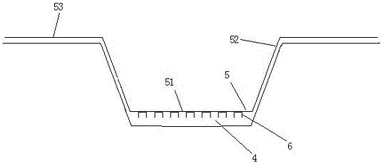
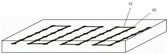
[0020] Please refer to Figure 1-Figure 5 , The landfill in this embodiment from top to bottom is the garbage landfill layer 1, gravel diversion layer 2, the on-film clay layer 3, and the under-film clay layer 4, the bottom of the on-film clay layer 3 and the garbage landfill The buried layer 1, the gravel guide layer 2 and the clay layer 3 on the membrane are wrapped with an impermeable membrane 5, and the underside of the impermeable membrane 5 is provided with an automatic resistivity acquisition system 6, which includes cables 61, The detection sensor 62 and the high-density electrical method 63. The cable 61 is arranged in a continuous bow shape on the lower side of the impermeable membrane 5. The detection sensor 62 is arranged on the cable 61, and the high-density electrical method 63 is fixedly connected to the end of the cable 61. The automatic resistivity acquisition system 6 is connected to the cloud service platform 7, the cloud service platform 7 is connected to the control terminal 8, and the control terminal 8 is connected to the automatic data processing system 9.
[0021] The automatic data processing system 9 includes an electric sensor system 91, an electric sensor signal conversion system 92, and a data processing and analysis system 93. The electric sensor system 91 is connected to the electric sensor signal conversion system 92, and the electric sensor signal conversion system is connected to the data processing and analysis system 92. 93. The electric sensor system 91 is buried in the monitored field, and establishes an electric field by supplying power underground and monitors the electric field potential; the electric sensor signal conversion system 92 receives the instruction of the data processing and analysis system 93 and selects the power supply of the electric sensor system 91 in the monitored field At the same time, the measurement signal of the electric sensor system 91 is transmitted to the data processing and analysis system 93; the data processing and analysis system 93 controls the various actions of the entire 3D online monitoring system, and simultaneously processes and analyzes the collected data in real time to determine the monitoring field The leakage point and pollution diffusion range of the area.
[0022] Both the automatic resistivity acquisition system 6 and the control terminal 8 are connected to the cloud service platform 7 through a wireless network.
[0023] The cable 61 includes a signal line 64 and a cable line 65 to realize electrical conduction and signal transmission simultaneously. The cable 61 extends along the edge of the impermeable membrane 5 to the opposite edge in the transverse direction of the bow shape. The cable 61 is in the bow shape. The distances in the longitudinal direction are equal. Of course, the cable 61 can also be routed according to the actual topography of the landfill.
[0024] The impermeable membrane 5 includes a bottom surface 51, two side surfaces 52 and two flat surfaces 53. Both ends of the bottom surface 51 are integrally formed with the side surface 52, and the other ends of the two side surfaces 52 are integrally formed with the flat surface 53.
[0025] The detection sensors 62 are arranged at equal intervals on the cable 61.
[0026] Theoretical basis: After leakage occurs in the landfill, the leachate invades into the vadose zone, and the resistivity of the soil decreases with the increase of water content; when the leachate continues to migrate downward to the saturated zone Because the leachate contains many ions, its resistivity is lower than that of water, so the resistivity of the pore water in the soil layer is reduced, which in turn reduces the resistivity of the soil layer. All in all, after the leachate in general landfills penetrates into the ground, it will reduce the resistivity of the soil and form a low-resistance area in the underground soil layer. The landfill leachate spreads horizontally and vertically in the soil layer, forming a three-dimensional plume pollution area. The area where the leachate diffuses can be monitored by detecting the abnormality of the resistivity of the underground soil.
[0027] After the leachate penetrates into the underground soil layer, the resistivity of the polluted medium will decrease, and the intrusion of petroleum pollutants will cause the resistivity of the polluted medium to increase. This electrical change law forms the basis of the resistivity monitoring system.
[0028] Working process: The automatic resistivity acquisition system 6 detects the resistivity change and then transmits it to the cloud service platform 7, the control terminal 8 and the automatic data processing system 9 in turn. The automatic data processing system 9 determines the leakage location through the coded measuring points. The sensor signal conversion system 92 controls the power supply and measurement status of each electrode of the electrode system through the cable, and the control terminal 8 issues work instructions to the electrical sensor signal conversion system 92 through the signal line 64 and the cable line 65 of the cable 61, supplies power to the electrodes, receives, and stores Store measurement data. The data collection result is automatically stored in the control terminal 8, and the control terminal 8 transmits the original data to the computer through communication software. The computer converts the data into the data format required by the processing software. After the corresponding processing module performs preprocessing such as distortion point removal and terrain correction, the resistivity contour map is made. The contour map is used for geological interpretation based on the change characteristics of apparent resistivity combined with drilling and geological survey data, and an interpretation map of geophysical prospecting results is drawn.
[0029] As the contaminated area changes, the range of the abnormal resistance area changes accordingly, and has a good corresponding relationship. The diffusion boundary, diffusion direction and diffusion speed of the leachate contaminated area can be obtained by comparing the monitoring results of different periods.
[0030] Can carry out remote and automatic operation, real-time data collection, processing, and monitoring, can control field equipment on the network anytime and anywhere, judge the working status of field equipment in time, and remotely guide local staff, effectively reducing personnel workload and operating costs , To meet the needs of users for remote monitoring anytime and anywhere; data can be permanently stored and deleted, easy to view historical curves, and intelligent automatic control; can effectively expand the monitoring range, realize arrangement monitoring, make the collected data more comprehensive and ensure the accuracy of real-time monitoring .

PUM

no PUM

Description & Claims & Application Information

We can also present the details of the Description, Claims and Application information to help users get a comprehensive understanding of the technical details of the patent, such as background art, summary of invention, brief description of drawings, description of embodiments, and other original content. On the other hand, users can also determine the specific scope of protection of the technology through the list of claims; as well as understand the changes in the life cycle of the technology with the presentation of the patent timeline. Login to view more.

Similar technology patents

Novel welding device

InactiveCN107116286AReduce staff workloadImprove work efficiency
Owner:诸暨市柯晶机械技术开发有限公司

Method and system for converting table data into game and electronic equipment

PendingCN112363691AReduce staff workloadImprove analysis conversion efficiency
Owner:HANGZHOU ELECTRONICS SOUL NETWORK TECH

Report data processing method and device

PendingCN114816352AReduce staff workloadImprove efficiency
Owner:INDUSTRIAL AND COMMERCIAL BANK OF CHINA

Production device for preparing radioactive iodine-131 through continuous feeding

ActiveCN110694565AReduced shield thickness requirementsReduce staff workload
Owner:NUCLEAR POWER INSTITUTE OF CHINA

Agricultural fertilizer application apparatus capable of uniformly applying fertilizer

PendingCN109379952AImprove work efficiencyReduce staff workload
Owner:南宁盛世凌云电子科技有限公司

Classification and recommendation of technical efficacy words

  • Expand the scope of monitoring
  • Reduce staff workload

Wide-angle security and protection monitoring device

InactiveCN108426143AReduce dead angleExpand the scope of monitoring
Owner:天津恒泰渤园科技发展有限公司

Computer health monitoring and managing system and method

InactiveCN101794251AExpand the scope of monitoring
Owner:INSPUR BEIJING ELECTRONICS INFORMATION IND

Product test method by monitoring users' using behavior

InactiveCN104503910AAvoid processing inefficienciesReduce staff workload
Owner:1VERGE INTERNET TECH BEIJING

Making method and device of scene subtitles

InactiveCN102082926AReduce staff workloadImprove efficiency
Owner:CHINA DIGITAL VIDEO BEIJING

River operation and maintenance management platform

PendingCN113658024AReduce staff workloadOptimize operation and maintenance management efficiency
Owner:浙江鼎胜环保技术有限公司

Agricultural fertilizer application apparatus capable of uniformly applying fertilizer

PendingCN109379952AImprove work efficiencyReduce staff workload
Owner:南宁盛世凌云电子科技有限公司

Method and system for converting table data into game and electronic equipment

PendingCN112363691AReduce staff workloadImprove analysis conversion efficiency
Owner:HANGZHOU ELECTRONICS SOUL NETWORK TECH
Why Eureka
Try Eureka