Method and device for measuring concentration of particles

A particle concentration and measurement method technology, which is applied in the field of particle concentration measurement methods and devices based on the light scattering principle, can solve the problems of inability to calibrate and measure the K value, increase the complexity of the system, etc., and achieve accurate and reliable detection results. Simple, cost-reducing effect

Active Publication Date: 2017-05-31
FOCUSED PHOTONICS +1
View PDF4 Cites 2 Cited by
  • Summary
  • Abstract
  • Description
  • Claims
  • Application Information

AI Technical Summary

Problems solved by technology

[0003] 1. The K value cannot be calibrated in real time. Generally, the K value will be calibrated after a period of time (such as 2 hours) after the particle measurement;
[0004] 2. The combination technology introduces the β-ray method or the oscillation balance method or the filter membrane weighing method, which increases the cost, increases the complexity of the system, and increases the overall volume of the device, making it impossible to carry out portable particle measurement

Method used


Image

  • Method and device for measuring concentration of particles
  • Method and device for measuring concentration of particles

Examples


Embodiment 1

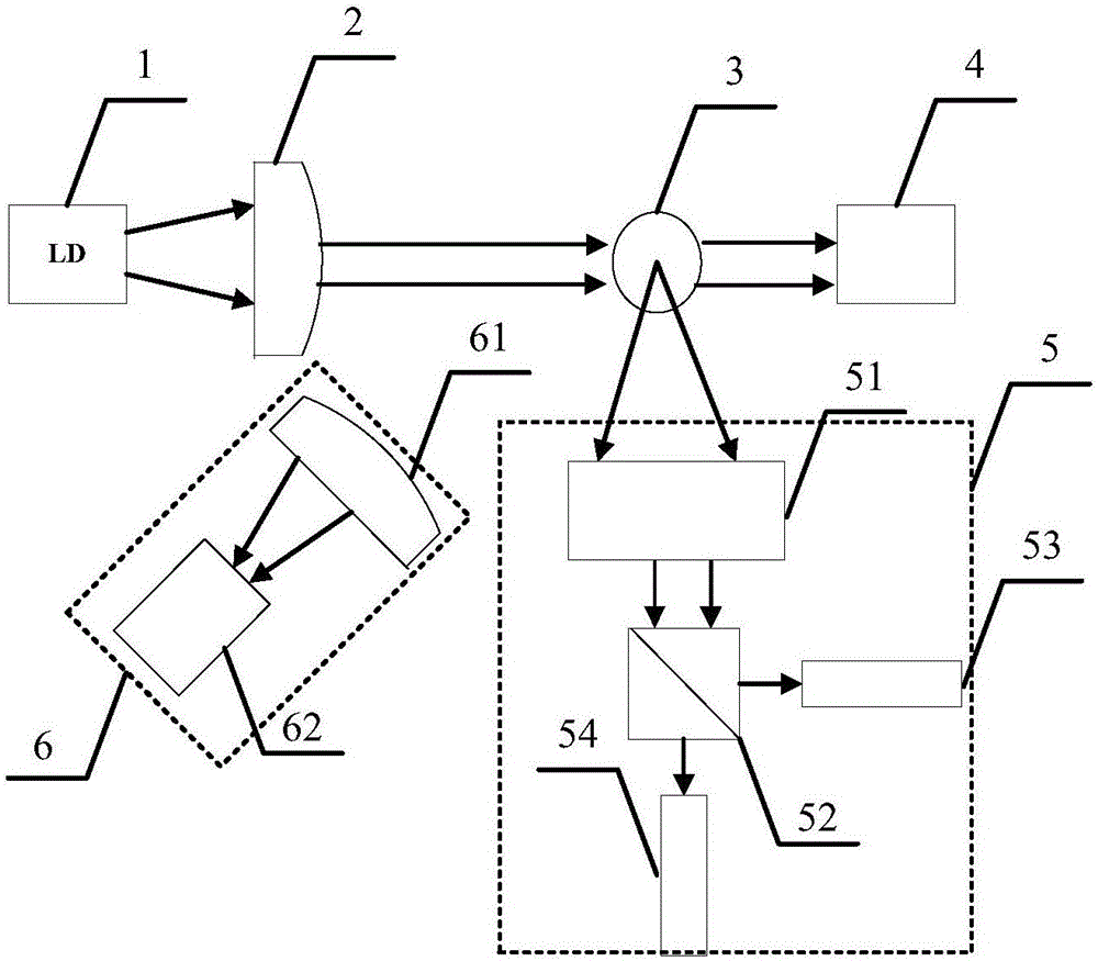
[0031] figure 1 Schematically provides a simplified structural diagram of the particle concentration measuring device of this embodiment, as figure 1 As shown, the particle concentration measuring device includes a light source 1, a collimating lens 2, a photosensitive area 3, and an optical trap 4, and the measuring device further includes:

[0032] Side scattering unit 5, said side scattering unit includes: collimating lens group 51, polarization beam splitter 52, first detector 53 and second detector 54; Said polarization beam splitter will collimate the side Splitting beams to the scattered light to form horizontally polarized light and vertically polarized light, the horizontally polarized light and vertically polarized light respectively enter the first detector and the second detector for detection;

[0033] The backscattering unit 6, the backscattering unit includes: a focusing lens 61 and a third detector 62, and the focused side scattered light enters the third dete...

Embodiment 2

[0046] This embodiment is an application example of the particle concentration measurement method and device of Embodiment 1 of the present invention in the field of atmospheric monitoring.

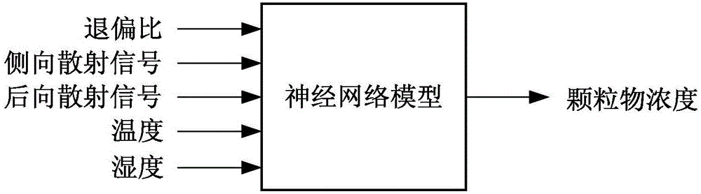
[0047] In this application example, the light source is a laser diode, the first detector, the second detector and the third detector are all PIN photodiodes, and the first detector outputs a vertically polarized light signal I of side scattered light 1 , the second detector outputs the horizontally polarized light signal I of the side scattered light 2 , so as to obtain the depolarization ratio D=I 1 / I 2 ; side scatter signal I 侧向 =I 1 +I 2 ; The third sensor outputs the backscatter signal I 后向 . At the same time, the ambient temperature T and relative humidity H are obtained through the temperature and humidity meter, and the depolarization ratio D, side scattering signal I 侧向 , Backscatter signal I后向 , ambient temperature T and relative humidity H are input into the established...


PUM


Abstract

The present invention relates to a method and a device for measuring concentration of particles, the method includes the following steps: (A1) establishment of a neural network model; (A2) acquisition of depolarization ratio, lateral scattering signals, backscattering signals, ambient temperature and relative humidity by measurement, and input of the depolarization ratio, the lateral scattering signals, backscattering signals, the ambient temperature and the relative humidity into the neural network model; wherein the depolarization ratio is lateral scattering light depolarization ratio; and (A3) output of the corrected concentration of the particles by the neural network model. The method and the device have the advantages of real-time correction of the concentration of the particles and accurate measurement results and the like.

Description

technical field [0001] The invention relates to the field of particle concentration monitoring, in particular to a particle concentration measurement method and device based on the principle of light scattering. Background technique [0002] At present, the measurement methods of particle concentration mainly include: standard weighing method, oscillating balance method, β-ray method and light scattering method. The light scattering method is widely used in the field of online particle monitoring because of its good repeatability and high sensitivity. However, the light scattering method is based on the principle of light scattering, which has poor adaptability to the environment. The scattering signal is easily affected by factors such as particle size, shape, refractive index, and environmental temperature and humidity. Concentration conversion coefficient K value for timing calibration. The combination of light scattering method and β-ray method, light scattering method ...

Claims


Application Information

Patent Timeline
Patent Type & Authority Applications(China)
IPC IPC(8): G01N15/06G06N3/08
CPCG01N15/06G01N2015/0693G06N3/08
Inventor 胡扬俊华道柱黄伟叶华俊
Owner FOCUSED PHOTONICS
Why Eureka
Try Eureka