Optical fiber sensor and device based on plasma resonance

A technology of plasmon resonance and optical fiber sensor, which is applied in the direction of measuring devices, instruments, scientific instruments, etc., can solve the problems of weak plasmon resonance intensity, poor comprehensive performance, and low sensitivity, and achieve simple and stable structure, increased strength, and expanded detection range effect

Inactive Publication Date: 2017-05-31
WUHAN INSTITUTE OF TECHNOLOGY
View PDF1 Cites 10 Cited by
  • Summary
  • Abstract
  • Description
  • Claims
  • Application Information

AI Technical Summary

Problems solved by technology

[0004] The technical problem to be solved by the present invention is to aim at the defects that the surface plasmon resonance intensity of the optical fiber sensor device of plasmon resonance in the prior art is weak, the distribution of the mode is scattered, it is not convenient for the measurement of the instrument, the sensitivity is low, and the comprehensive performance is poor, providing An optical fiber sensor and device based on plasmon resonance that is easy to detect, easy to manufacture, high in sensitivity and better in comprehensive performance

Method used


Image

  • Optical fiber sensor and device based on plasma resonance
  • Optical fiber sensor and device based on plasma resonance

Examples


Embodiment Construction

[0021] In order to make the object, technical solution and advantages of the present invention clearer, the present invention will be further described in detail below in conjunction with the accompanying drawings and embodiments. It should be understood that the specific embodiments described here are only used to explain the present invention, not to limit the present invention.

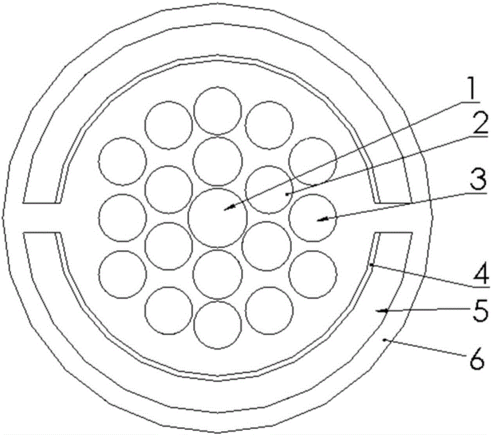
[0022] like figure 1 As shown, in the optical fiber sensor based on plasmon resonance of the embodiment of the present invention, multi-layer air holes are arranged in the optical fiber 6, and the multi-layer air holes include a central air hole 1, a first air hole layer 2, a second air hole layer 3 and Fan-shaped air holes 5; the first air hole layer 2 and the second air hole layer 3 all include a plurality of independent air holes; wherein:

[0023] The central air hole 1 is arranged at the center position of the optical fiber 6, and the first air hole layer 2, the second air hole layer 3 and th...


PUM

PropertyMeasurementUnit
refractive indexaaaaaaaaaa

Abstract

The invention discloses an optical fiber sensor and device based on plasma resonance. The optical fiber of the sensor is internally provided with a plurality of layers of air holes, and the air holes include a central air hole, a first air hole layer, a second air hole layer and a fan annular air hole which are formed from inside to outside, wherein each of the first air hole layer and the second air hole layer contains a plurality of independent air holes; the central air hole is formed in the center of the optical fiber, the first air hole layer, the second air hole layer and the fan annular air hole are arranged symmetrically with the central air hole as a symmetrical center, each of the first air hole layer and the second air hole layer has a hexagonal shape, and the side of the fan annular air hole, adjacent to the center, is coated with a film; and the central air hole and the second air hole layer are filled with air mediums, the first air hole layer is filled with a metal medium, and the fan annular air hole is filled with a liquid medium to be detected. The optical fiber sensor has the advantages of simple manufacture, high sensitivity and better comprehensive performance, the detection range of the sensor can be effectively enlarged, and wider application demands can be met.

Description

technical field [0001] The invention relates to the technical field of plasma resonance sensing, in particular to an optical fiber sensor and device based on plasma resonance. Background technique [0002] Optical fiber sensor is produced with the appearance of optical fiber and the development of optical fiber communication. It is a device that uses light as the carrier and optical fiber as the transmission medium to realize the sensing of the measured parameters. In the 1980s, low-loss silica optical fiber was successfully drawn and commercialized, making optical fiber sensing technology show broad application prospects. Since then, research on optical fiber sensors has always been a frontier topic in the development of sensor technology. In the late 1990s, driven by optical communication technology, optical fiber sensing technology showed industrial development and gradually applied to the five major fields of medicine and biology, national defense and military, electri...

Claims


Application Information

Patent Timeline
Patent Type & Authority Applications(China)
IPC IPC(8): G01N21/552
CPCG01N21/553
Inventor 李芳魏来周剑心
Owner WUHAN INSTITUTE OF TECHNOLOGY
Why Eureka
Try Eureka