Eureka AIR delivers breakthrough ideas for toughest innovation challenges, trusted by R&D personnel around the world.

Connecting structure for vertically fixing probe rod and probe rod fixing method

A connection structure and probe technology, applied in scanning probe technology, scanning probe microscopy, measuring devices, etc., can solve the difficulty of adjusting the verticality of the probe axis, affecting the quality of the needle tip of the probe, and difficult to achieve short Probe rod vertical and other problems, to achieve the effect of small resistance torque, improved verticality, simple connection structure

Active Publication Date: 2017-05-31
GUIZHOU UNIV
View PDF10 Cites 2 Cited by
  • Summary
  • Abstract
  • Description
  • Claims
  • Application Information

AI Technical Summary

Problems solved by technology

[0004] In the ordinary device for making scanning tunneling microscope probes, it is difficult to realize the verticality of the short probe rod by the connection structure of the fixed probe rod. Generally, it is necessary to use an instrument to adjust the verticality of the probe axis through the upper adjustment frame or the connection structure of the fixed probe rod. degree, and it is difficult to adjust the verticality of the probe axis; the probe axis is not vertical, which affects the needle tip of the probe on the probe axis and affects the quality of the probe tip

Method used


Image

  • Connecting structure for vertically fixing probe rod and probe rod fixing method
  • Connecting structure for vertically fixing probe rod and probe rod fixing method
  • Connecting structure for vertically fixing probe rod and probe rod fixing method

Examples


Embodiment Construction

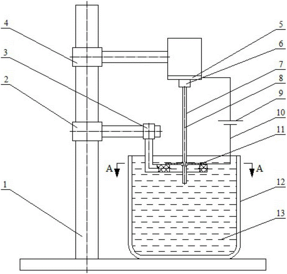
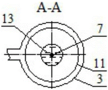
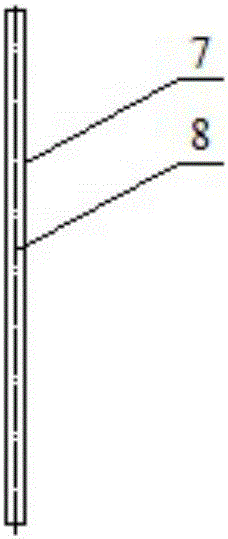
[0041] In the accompanying drawings of the manual: 1 bracket; 2 lower adjustment frame; 3 lower adjustment tray; 4 upper adjustment frame; 5 conductive plate; 6 probe clip; 7 short probe rod; 8 probe axis; Conductive ring; 12 beaker; 13 electrolyte; 14 short probe at one end; 15 long probe rod; 16 long probe rod at one end; 17 long probe rod with magnetic end; 18 magnet; 19 conductive glue; 20 two Tip short probe; a height of magnetic material.

[0042] In the present invention, the short probe rod, the long probe rod, the long probe rod with a pointed end and the long probe rod with a magnetic one end are all probe rods, and the short probe with one end and the short probe with both ends are both probe rods. for the probe.

[0043] A common device for making scanning tunneling microscope probes and making a short-pointed probe such as figure 1 ~shown in 4; make one end pointed long probe stick as Figure 5 ~7 shown; a long probe stick with a magnetic end as shown in Figu...


PUM


Abstract

The invention discloses a connecting structure for vertically fixing a probe rod and a probe rod fixing method. The connecting structure comprises a conducting plate (5), wherein a magnet (18) is adsorbed at the upper side of the conducting plate (5); the conducting plate (5) is connected with an upper regulating frame (4); the lower surface of the conducting plate (5) is a plane; conducting glue (19) is coated on the lower surface of the conducting plate (5). The method comprises the following steps of 1, manufacturing the probe rod with one sharp and long end; 2, manufacturing a magnetic probe rod with one sharp and long end; 3, uniformly coating the conducting glue on the lower surface of the conducting plate; 4, vertically fixing the magnetic probe rod with one sharp and long end on the lower surface of the conducting plate. The connecting structure disclosed by the invention solves the problems that the connecting structure for fixing the probe rod in the prior art is difficult to realize the verticality of a short probe; an external instrument is needed; the axial line perpendicularity of the probe is regulated through the upper regulating frame or the connecting structure for fixing the probe rod; the regulation of the axial line perpendicularity of the probe is difficult; when the axial line of the probe is not perpendicular, the pinpoint of the probe on the axial line of the probe is influenced; the pinpoint manufacturing quality of the probe is influenced.

Description

technical field [0001] The invention relates to equipment for making scanning tunneling microscope probes, in particular to a connection structure for vertically fixing a probe bar and a method for fixing the probe bar. Background technique [0002] Common setup for making scanning tunneling microscope probes (see figure 1 ) includes a bracket, a lower adjustment frame, and a lower adjustment tray; an upper adjustment frame, a conductive plate, a probe clip, a battery, a wire, a conductive ring and a beaker, wherein the conductive plate and the probe clip form a connection structure for fixing the probe rod; Both the adjustment frame and the upper adjustment frame are connected with the bracket, the conductive plate is connected with the upper adjustment frame, and the probe clip is connected with the conductive plate; the conductive ring is in the beaker, the center of the stainless steel conductive ring has a hole, and the conductive ring is fixed on the lower adjustment t...

Claims


Application Information

Patent Timeline
Patent Type & Authority Applications(China)
IPC IPC(8): G01Q70/16
CPCG01Q70/16
Inventor 丁召许筱晓
Owner GUIZHOU UNIV
Why Eureka
Eureka Blog
Learn More