Synchronous generator rotor winding turn-to-turn short circuit diagnosis method based on double coils

A technology for synchronizing generator and rotor windings, which is applied in electrical winding testing, motor generator testing, and electrical measurement. Magnetic flux and other problems, achieve high anti-interference ability and diagnostic accuracy, and prevent the deterioration of inter-turn short circuit faults in synchronous generator rotor windings

Active Publication Date: 2017-05-31
NORTH CHINA ELECTRIC POWER UNIV (BAODING)
View PDF5 Cites 16 Cited by
  • Summary
  • Abstract
  • Description
  • Claims
  • Application Information

AI Technical Summary

Problems solved by technology

The inter-turn short-circuit fault of the rotor winding of a certain magnetic pole affects the local relevant electrical quantities, and has a relatively small impact on the entire generator. Therefore, the method of excitation current, imaginary power, expected potential, shaft voltage and end leakage It is difficult to detect the inter-turn short circuit fault of the rotor winding of the hydro generator sensitively
The rotor of the hydro-generator has a salient pole structure, and the winding is centralized. The detection coil method most commonly used by the turbo-generator is not suitable for the hydro-generator, because the detection coil can only detect the magnetic flux leakage concentrated at the slot of the rotor. pass, unable to detect the distributed main flux of the hydro-generator
[0005] In conclusion, although much attention has been paid to the diagnosis of inter-turn short-circuit faults in the rotor windings of synchronous generators, practical and high-performance online detection methods are seriously lacking. Some methods are only suitable for turbogenerators in synchronous generators, not Hydrogenerator

Method used


Image

  • Synchronous generator rotor winding turn-to-turn short circuit diagnosis method based on double coils
  • Synchronous generator rotor winding turn-to-turn short circuit diagnosis method based on double coils
  • Synchronous generator rotor winding turn-to-turn short circuit diagnosis method based on double coils

Examples


specific Embodiment approach

[0031] A specific embodiment of the present invention comprises the following steps:

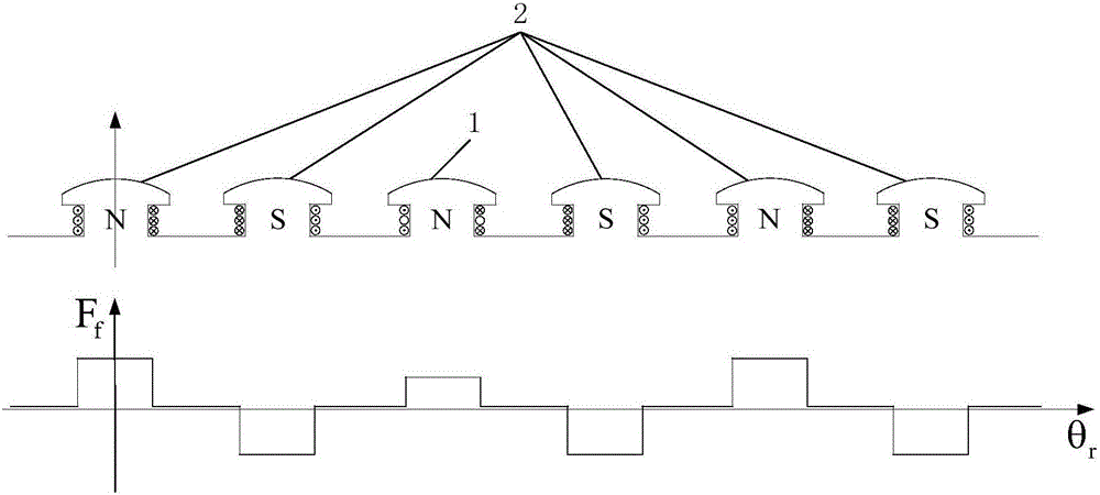
[0032] Two U-shaped detection coils are installed in the radial direction at a certain distance on the stator core section inside the synchronous generator. The output ports of the two U-shaped detection coils are connected in parallel with high resistance resistors with the same resistance value, and the two U-shaped detection coils are collected by the data acquisition device. The voltage signal of the output port of the U-shaped detection coil;

[0033] During the operation of the generator, the voltage signals at the outlets of the two U-shaped detection coils collected by the data acquisition device are processed in real time, and the output voltages of the two U-shaped detection coils are differenced or added. When the result exceeds the set threshold , it is determined that the synchronous generator has an inter-turn short circuit fault in the rotor winding.

[0034] The distance bet...


PUM


Abstract

The invention discloses a synchronous generator rotor winding turn-to-turn short circuit diagnosis method based on double coils. The method includes following steps: A, radially mounting two U-shaped detection coils on a stator iron core section inside a synchronous generator at a certain distance, parallelly connecting output ports of the U-shaped detection coils with high-resistance-value resistors with an equal resistance value, and utilizing a data collection device to collect voltage signals of the output ports of the U-shaped detection coils; B, in an operating process of the generator, processing the voltage signals of two U-shaped detection coil outlets collected by the data collection device in real time, subtracting or adding output voltage of the U-shaped detection coils, and when a result exceeds a set threshold value, judging that the synchronous generator has a rotor winding turn-to-turn short circuit fault. By the method, the defects of the prior art can be improved, and diagnosis level of the faults of this kind is elevated.

Description

technical field [0001] The invention relates to the technical field of generators, in particular to a double-coil-based method for diagnosing inter-turn short-circuits in rotor windings of synchronous generators. Background technique [0002] Turn-to-turn short-circuit fault of rotor winding is a common fault of synchronous generator. The further deterioration of this fault may cause aggravated vibration of synchronous generator, and even cause problems such as one-point grounding of the rotor, two-point grounding of the rotor, loss of magnetization, and magnetization of the large shaft. Therefore, enough attention should be paid to the inter-turn short-circuit fault of the rotor winding of synchronous generators. It is the future development trend to use the online diagnosis method to detect the inter-turn short-circuit fault of the synchronous generator rotor winding. [0003] The current on-line diagnosis methods for inter-turn short circuit faults of synchronous generato...

Claims


Application Information

Patent Timeline
Patent Type & Authority Applications(China)
IPC IPC(8): G01R31/34G01R31/06
CPCG01R31/346G01R31/72
Inventor 武玉才王逸仙蔡波冲马倩倩
Owner NORTH CHINA ELECTRIC POWER UNIV (BAODING)
Why Eureka
Try Eureka