
Method for measuring and detecting beam dosage distribution

A dose distribution and dose technology, applied in the field of dose verification equipment, can solve problems such as lack of synchronization, large imaging errors, and high prices

Active Publication Date: 2017-05-31
JIANGSU SUPERSENSE TECH CO LTD
View PDF6 Cites 3 Cited by
  • Summary
  • Abstract
  • Description
  • Claims
  • Application Information

AI Technical Summary

Problems solved by technology

This measurement has three main disadvantages: First, due to the movement of the patient's body, soft tissues and organs have already undergone displacement and deformation compared with the treatment, so the PET image needs to be processed with complex registration processing with the CT image of the treatment terminal. Increased the difficulty of measurement result processing while reducing measurement accuracy
The second is that it takes a certain amount of time (about 20 minutes) from the end of the treatment to the PET scan. At this time, 15O (half-life of 2 minutes) basically decays, and most of 13N (half-life of 10 minutes) decays, so only part of it can be measured. 11C (half-life 20 minutes) information, lost valuable information
Third, the reconstruction algorithms used in clinical PET are all designed for the injection of positron drugs (positron activity is in the mCi order), and cannot be well applied to patients with low positron activity after proton / heavy ion therapy. However, the imaging error is large, which reduces the accuracy of the measurement
Even when this technology matures, it will be very expensive
[0005] At present, the dose measurement instrument used for intraoperative verification is mainly online PET, which is installed on the proton / heavy ion therapy terminal to measure while irradiating. It is necessary to build a large ring detector, which is bulky and expensive, and has not yet been widely used in clinical practice. application
And it is not real-time online measurement, real synchronization cannot be achieved, and PET scan is required after the treatment, which takes a long time

Method used


Image

  • Method for measuring and detecting beam dosage distribution
  • Method for measuring and detecting beam dosage distribution

Examples


Embodiment Construction

[0026] Hereinafter, the present invention will be further described with reference to the drawings and specific implementations:

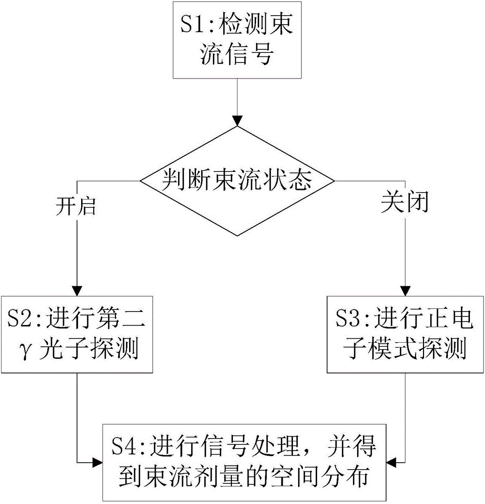
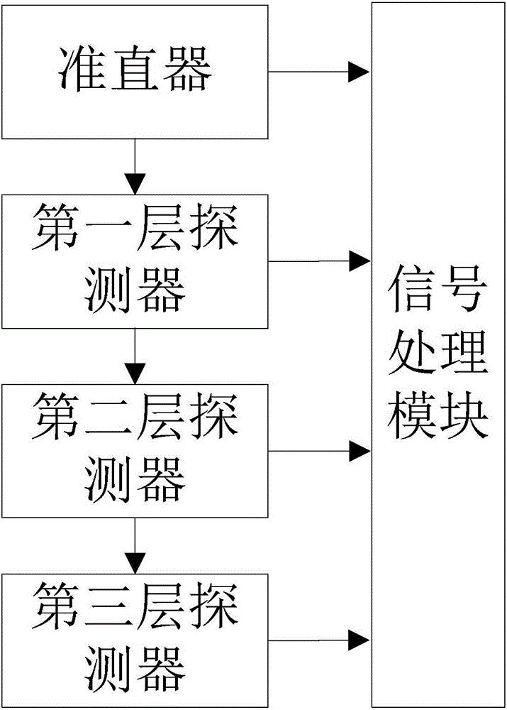
[0027] Such as figure 1 with figure 2 As shown, the method for measuring and detecting beam dose distribution of the present invention is mainly applied to beam dose distribution measuring equipment, which mainly includes the following steps:

[0028] S1: The computer detects a beam signal and judges the beam state. If it is in the on state, then it goes to S11, if it is in the off state, it goes to S3;

[0029] S11: Perform anti-coincidence detection of beam signals through a collimator;

[0030] S2: The detector module detects the second gamma photon and transmits the detected second gamma photon signal to the computer; S2 specifically includes the following sub-steps:

[0031] S21: Obtain the X-ray signal and the first gamma photon signal through the first layer detector;

[0032] S22: The second gamma photon signal is detected by the second layer detect...


PUM


Abstract

The invention discloses a method for measuring and detecting beam dosage distribution. The method comprises following steps that S1, a computer detects a beam signal and judges the state of the beam, if the beam is in the starting state, the step 2 is entered and if the beam is in the closed state, the step 3 is entered; step 2, a detector module detects second gamma photon, and transmits a detected second gamma photon signal to the computer; S3, the detector module carries out positive electronic mode detection and transmits a detected positive electrode mode signal to the computer; and step 4, the computer carries out signal processing on the second gamma photon signal and the positive electronic mode signal which are obtained through detection, and obtains spatial distribution of the beam dosage. According to the invention, distribution of the beam dosage after the beam is after the beam passes through a simulated human body, so emission dosage of a beam emission end is further detected and accuracy of the detected dosage distribution is judged.

Description

Technical field [0001] The invention belongs to the technical field of dose verification equipment, and in particular relates to a method for measuring and detecting beam dose distribution. Background technique [0002] The principle of preoperative dose verification is to use a phantom instead of the patient, irradiate the proton / heavy ion terminal with a designed treatment plan, and actually measure the spatial distribution of the proton beam / heavy ion beam dose in the phantom, and compare it to expectations Comparing the spatial distribution of, verify whether there is a deviation to ensure that the accelerator is working in a normal state. [0003] The basic technical route for intraoperative and postoperative dose verification of proton / heavy ion therapy is positron emission tomography (PET). The principle of this technical route is as follows: where protons / heavy ions deposit doses after entering the human body, they will react with the nuclei in the human body to generate p...

Claims


Application Information

Patent Timeline
Patent Type & Authority Applications(China)
IPC IPC(8): G01T1/29
CPCG01T1/29
Inventor 周荣许纹健李磊孙熙杉薛会吕凌俊王敏刘飞
Owner JIANGSU SUPERSENSE TECH CO LTD
Learn More