Earthquake diffracted-wave separation method and device

A diffraction wave and seismic gun technology, applied in the field of seismic diffraction wave separation, can solve the problems of poor amplitude integrity and waveform consistency of diffracted waves, and low imaging resolution of carbonate rock strata.

Active Publication Date: 2017-05-31
INST OF GEOLOGY & GEOPHYSICS CHINESE ACAD OF SCI
View PDF8 Cites 20 Cited by
  • Summary
  • Abstract
  • Description
  • Claims
  • Application Information

AI Technical Summary

Problems solved by technology

However, the kinematic characteristics of diffracted waves and reflected waves in the collected 3D shot data are relatively similar, and it is difficult to effectively process them only by conventional kinematic wave field separation methods, resulting in low imaging resolution of carbonate strata structures.
[0004] Aiming at the poor amplitude integrity and waveform consistency of the diffraction waves separated by the above-mentioned seismic diffraction wave separation method, no effective solution has been proposed so far.

Method used


Image

  • Earthquake diffracted-wave separation method and device
  • Earthquake diffracted-wave separation method and device
  • Earthquake diffracted-wave separation method and device

Examples


Embodiment 1

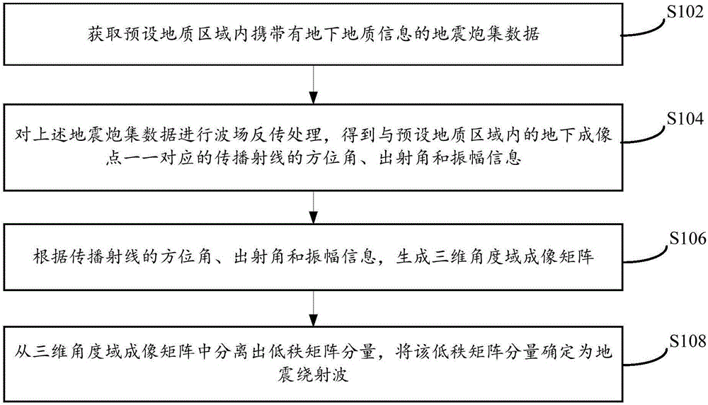
[0037] see figure 1 A flow chart of a seismic diffraction wave separation method shown, the method includes the following steps:

[0038] Step S102, acquiring seismic shot data carrying underground geological information in a preset geological area; wherein, the underground geological information includes geological structure information and geological lithology change information; specifically, the underground geological information can be rock structure, fault , karst caves and lithological mutation points and other information;

[0039] Step S104, performing wavefield backpropagation processing on the above-mentioned seismic shot data to obtain the azimuth angle, exit angle and amplitude information of the propagating rays corresponding to the underground imaging points in the preset geological area;

[0040] Step S106, according to the azimuth, exit angle and amplitude information of the propagating ray, generate a three-dimensional angle domain imaging matrix; specifica...

Embodiment 2

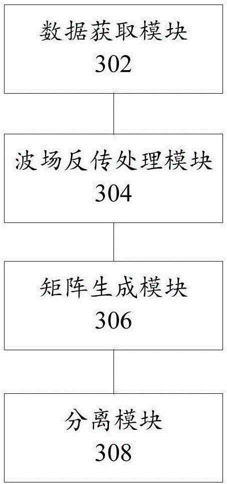
[0074] Corresponding to the above method embodiment, see image 3 A structural schematic diagram of a seismic diffraction wave separation device shown, the device includes the following parts:

[0075] A data acquisition module 302, configured to acquire seismic shot data carrying underground geological information in a preset geological area; wherein the underground geological information includes geological structure information and geological lithology change information;

[0076] The wave field back-propagation processing module 304 is used to perform wave field back-propagation processing on the seismic shot data, and obtain the azimuth angle, exit angle and amplitude information of the propagating rays corresponding to the underground imaging points in the preset geological area;

[0077] A matrix generation module 306, configured to generate a three-dimensional angle domain imaging matrix according to the azimuth, exit angle and amplitude information of the propagating ...


PUM


Abstract

The invention provides an earthquake diffracted-wave separation method and device and relates to the technical field of earthquake exploration. The method comprises the steps that earthquake shot gather data carrying underground geological information in a preset geological area is obtained; single-shot preprocessing data obtained by preprocessing the earthquake shot gather data and a preset migration velocity model are input into a three-dimensional single-shot angle-domain imaging formula, wave field opposite-transmission processing is conducted on the earthquake shot gather data to obtain azimuth angles, emergence angles and amplitude information of propagation rays corresponding to underground imaging points in the preset geological area in a one-to-one mode; according to the azimuth angles, emergence angles and amplitude information of the propagation rays, a three-dimensional single-shot angle-domain imaging matrix is generated; low-rank matrix components are separated out of the three-dimensional single-shot angle-domain imaging matrix through a preset three-dimensional diffracted-wave separation model, and the low-rank matrix components are determined as earthquake diffracted waves. The integrity and waveform consistency of separated diffracted-wave amplitude are improved, and further the resolution ratio of geological structure imaging is improved.

Description

technical field [0001] The invention relates to the technical field of seismic exploration, in particular to a seismic diffraction wave separation method and device. Background technique [0002] Carbonate oil and gas reservoirs have become the main field for increasing reserves and production of oil and gas resources. However, the structure of carbonate strata in some areas is very special, which makes the formation and distribution of carbonate reservoirs more complex, resulting in the inability to finely image geological bodies such as karst caves and fractures. [0003] In the prior art, seismic exploration in the petroleum industry mainly uses reflection waves, but the resolution of reflection wave exploration is limited, and it is impossible to effectively identify geological bodies with carbonate strata structure. At the same time, since the seismic response of the geological body of the carbonate strata structure is diffracted waves, effective separation of diffract...

Claims


Application Information

Patent Timeline
Patent Type & Authority Applications(China)
IPC IPC(8): G01V1/28
CPCG01V1/28G01V1/302G01V1/325G01V1/36G01V2210/512G01V2210/56G01V2210/632G01V2210/67
Inventor 于彩霞王彦飞
Owner INST OF GEOLOGY & GEOPHYSICS CHINESE ACAD OF SCI
Why Eureka
Try Eureka