Method for generating solid modulating plasma photonic crystals with four refractive indexes
A plasma and photonic crystal technology, applied in the field of plasma application technology and optics, to achieve a wide range of application prospects and application fields, with a wide range of effects
- Summary
- Abstract
- Description
- Claims
- Application Information
AI Technical Summary
Problems solved by technology
Method used
Image

Examples
Embodiment 1
[0025] Example 1, the device used to produce a solid-modulated plasmonic photonic crystal with four refractive indices.
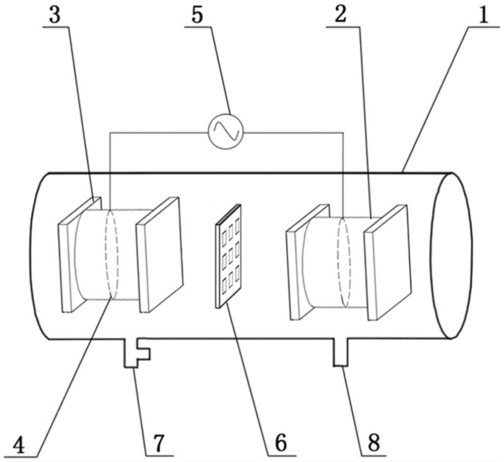
[0026] Such as figure 1 As shown, the device used in the present invention is specifically: two airtight dielectric containers are symmetrically arranged in a horizontal cylindrical vacuum reaction chamber 1, and water is injected into the airtight dielectric container to form two opposite water electrodes. 2. The two water electrodes 2 are electrically connected with the plasma generating power source 5 outside the vacuum reaction chamber 1 . In this embodiment, the water electrode 2 is made of a plexiglass tube sealed by glass baffles 3 at both ends, the plexiglass tube is filled with water, and a copper ring 4 is set in the plexiglass tube. The two copper rings 4 are respectively electrically connected to the positive pole and the negative pole of the plasma generation power supply 5 through power lines. The thickness of the glass block 3 is between 1...
Embodiment 2
[0033] combine figure 1 with figure 2 , a vacuum reaction chamber 1 is set, an air inlet 7 and an air outlet 8 are provided on the wall body of the vacuum reaction chamber 1, and an argon gas bottle ( figure 1 not shown). Two water electrodes 2 opposite to each other are installed in the vacuum reaction chamber 1 . The water electrode 2 is composed of a plexiglass tube sealed with glass baffles 3 on both sides and filled with water, and a built-in copper ring 4 is electrically connected to the plasma generating power supply 5 outside the vacuum reaction chamber 1 .
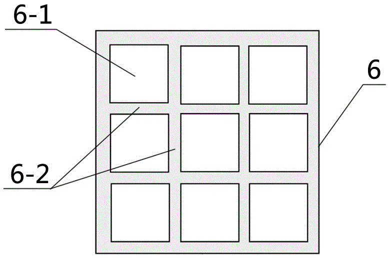
[0034] A solid frame 6 with a thickness of 2mm is arranged between the two water electrodes 2, the solid frame 6 is an acrylic plate, the plane where it is located is perpendicular to the axes of the two water electrodes 2, and the two sides are close to the two water electrodes 2 end face. Nine square through holes 6 - 1 with equal size and side length of 8 mm are opened in the inner area of the solid fram...
Embodiment 3
[0038] Compared with Example 2, this example differs in that: discharge gas pressure P=0.35atm, voltage amplitude U=2.00kV, discharge frequency f=55kHz, argon volume content φ=20%.
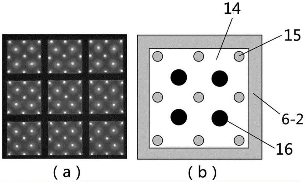
[0039] see Figure 4 , the photo of the plasma photonic crystal formed by solid (solid edge 6-2 with a width of 2mm), gas (that is, the gas in the second undischarged region 17) and plasma periodically arranged in this embodiment (common camera) such as Figure 4 (a), Figure 4 A partial schematic diagram of a cycle in (a) as Figure 4 (b) shown. Figure 4 The gas shown in (b) (that is, the gas in the second undischarged region 17), the third plasma 18, the solid edge 6-2, and the fourth plasma 19 have different refractive indices; wherein the second undischarged region 17 The refractive index of the gas is 1; the refractive index of the third plasma 18 and the fourth plasma 19 are both less than 1, and the refractive index of the third plasma 18 is slightly smaller than the refractive index o...
PUM
 Abstract
Description
Claims
Application Information
 - R&D
- Intellectual Property
- Life Sciences
- Materials
- Tech Scout
- Unparalleled Data Quality
- Higher Quality Content
- 60% Fewer Hallucinations
Browse by: Latest US Patents, China's latest patents, Technical Efficacy Thesaurus, Application Domain, Technology Topic, Popular Technical Reports.
© 2025 PatSnap. All rights reserved.Legal|Privacy policy|Modern Slavery Act Transparency Statement|Sitemap|About US| Contact US: help@patsnap.com